Engineering in Plain Sight by Hillhouse
Ref: Grady Hillhouse (2022). Engineering in Plain Sight. No Starch Press.
___________________________________________________________________________
Summary
What is a substation? What are those strange green boxes near traffic lights on the side of a road? How does clean water get to my house? Engineering in Plain Sight is a a detailed look at the ubiquitous yet misunderstood infrastructure that we see in our daily lives, including the electrical grid, the telecommunications networks, transportation, water, sewer, and storm infrastructure, construction sites and more.
___________________________________________________________________________
Ch 1 Electrical Grid
Overview of the Electrical Grid
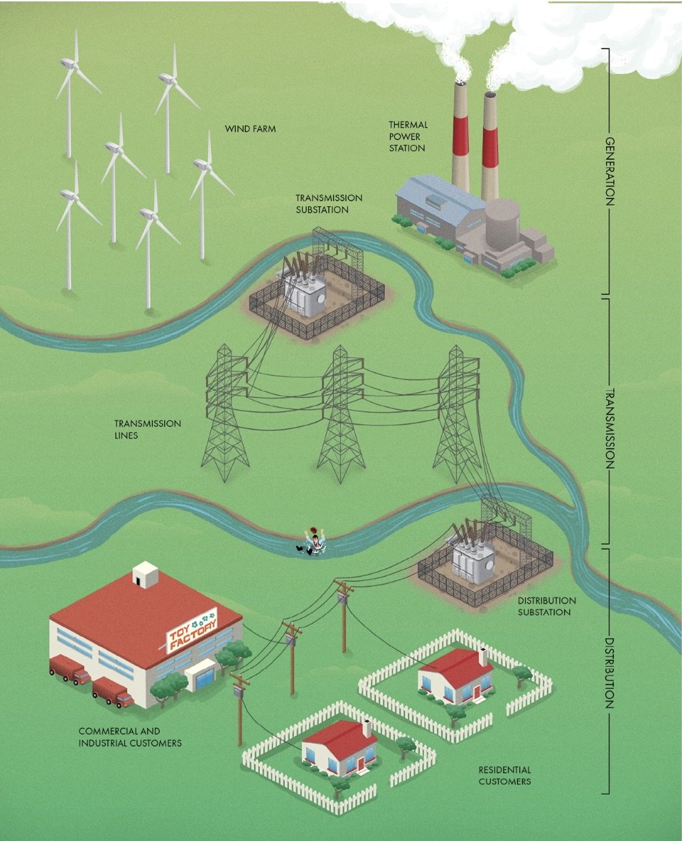
Electrical Grid: Huge, interconnected networks of electricity producers and users. To get a sense of scale, only five major power grids cover all of North America. The electrical grid includes generation, transmission, and distribution. Substations serve as the connection points between the major parts.
Generation: Production of Power. Solar farms generate electricity when the sun is up, but none when the sun is down. Wind farms generate electricity depending on weather, with peak output during times when winds are strong and consistent. Nuclear plants generate consistent power with little ability to ramp up or down, while other thermal power stations like coal or natural gas plants can adjust their output somewhat according to changing demands. Hydropower plants are the most responsive, often with the ability to start and stop generation within seconds or minutes.
Many of the methods we use to generate power are just different ways of boiling water. Plants that use this method are called thermal power stations because they rely on heat to create steam. The steam passes through a turbine, which is coupled to an AC generator connected to the power grid.
Transmission: Moving electricity from centralized power plants to populated areas.
Distribution: Delivering the electricity to every individual customer.
1 Electrical Generation System
Electrical demand peaks during the day when people are using lots of electricity, particularly on scorching or freezing days when many are using HVAC. To avoid brownouts and blackouts, generation must be continuously adjusted up or down to match electrical demands on the grid. This process is called load following. If the worst comes, and there is not enough electricity to meet demands, grid managers will require that some customers be temporarily disconnected (called load shedding) to reduce demands and avoid a total collapse. Normally these disconnections happen on a rolling basis of 15-30 min to spread out the inconvenience of lost service, so they are often known as rolling outages.
Rather than a constant flow of current in a single direction (‘direct current- DC’), the vast majority of the power grid uses alternating current (‘AC’), where the direction of voltage and current is continually switching. The benefit of having the current alternate is that its voltage can easily be stepped up or down using a transformer. In North America, this happens at 60 cycles per second, giving electrical infrastructure that familiar low hum. Power is usually generated and transmitted on three individual lines called phases (labeled A, B, and C), each of which has voltage offset from its neighbors. Creating electricity in three distinct phases provides a smooth supply that overlaps, so there is never a moment when all phases have zero voltage. A three-phase supply also uses fewer equivalent conductors than a single-phase supply to carry the same amount of power, making it more economical. You’ll notice that almost all electrical infrastructure shows up in groups of three, with each conductor or piece of equipment handling an individual phase of the supply.
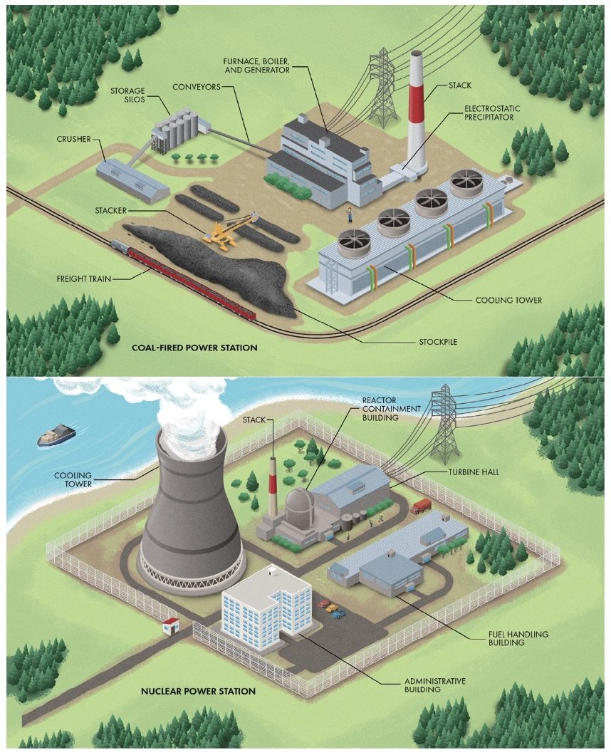
Coal Power Station: Electricity producing plants that process and burn thousands of tons of coal daily. Most of the visible infrastructure is there to offload, store, crush, and transport the coal to the furnace or boiler. The primary way to move this much fuel efficiently is by freight train. Coal is delivered in large chunks, so from the stockpiles, it must go into a crusher to reduce its size for more efficient burning. Between each step of the fuel handling, large covered conveyor belts transport the coal. Storage silos protect the crushed coal from the elements. From there, it makes its final journey to the furnace and boiler.
Natural Gas–Fired Power Station: Electricity producing plants that are fed by underground gas pipelines. F
Flue Gas: The air from the combustion of fossil fuels in both coal- and gas-fired plants; carries dangerous pollutants like ash and nitrous oxides. Environmental regulations require that flue gas be rid of the worst of these pollutants before it’s released into the atmosphere since they can be harmful to humans and animals. Many different facilities are used to remove pollutants from flue gas, including baghouses that use fabric filters, electrostatic precipitators that capture particles through static cling, and scrubbers that clean the air by spraying a fine mist, catching dust and ash. After passing through these facilities, the flue gas can be released through a stack. Although these tall chimneys don’t clean the flue gas directly, they do help manage pollution by releasing it high enough to be dispersed in the air (since dilution is sometimes the solution to pollution).
Nuclear Power Station: An electricity producing plant that relies on the carefully controlled fission of radioactive materials. This process happens in a nuclear reactor, often evident from the outside as a pressurized containment building with a domed roof. The reactor building usually has an outside armoring layer of thick concrete as a precaution against natural disasters or sabotage. A separate fuel handling building is generally used for receipt, inspection, and storage of nuclear fuel. Nuclear plants sometimes also have a stack, but it is not for releasing flue gas. In some reactors, the water used to drive the turbine comes into direct contact with radioactive fuel, which can create gases like H and O that become mildly radioactive themselves. The tall, solitary stack seen at some nuclear plants allows for safe ventilation of those gases.
1 Electrical Power Generation Stations
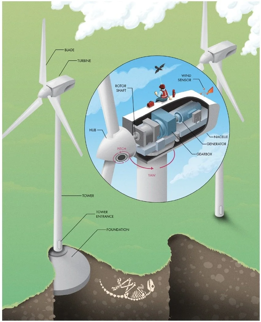
Wind Farm: An electricity producing plant that consists of multiple turbines that capture wind energy and convert it into electricity. Utility-scale turbines are usually rated around 1-2 MW each, but units as large as 10 MW have been installed. That’s enough to power about 5,000 households with a single turbine! From the outside, you can see the hub with attached blades and the nacelle, the outer housing for the rest of the turbine’s equipment. Inside the nacelle are the rotor shaft, gearbox, generator, and other equipment. A turbine is most efficient when the tip of the blades is moving ~4-7x the speed of the wind. Turbines operate at their best when facing directly into the wind. Older windmills used a large tail to keep this proper orientation, called yaw. Modern turbines use a wind sensor atop the nacelle to measure both the speed and direction of the wind. Most turbines also include a way to adjust the angle, or pitch, of each blade. When the wind is too fast for the turbine to operate efficiently, the blades are furled (that is, tilted so only the edge of the blade faces into the wind) to reduce the forces on the turbine. The theoretical maximum efficiency that can be extracted (called the Betz limit) is ~60%. The slender blades of the turbine are carefully designed to capture as much energy as possible without slowing the air stream too much.
1 Wind Farm
Transmission Towers
Electricity flowing in a circuit has two important properties: voltage is the amount of electric potential (somewhat equivalent to the pressure of a fluid in a pipe), and current is the flow rate of an electric charge (like the flow rate of a fluid in a pipe). These two properties are related to the total amount of power traveling through a line. The amount of wasted power from resistance is related to the current in the line, so more current means more wastage. If you increase the voltage of the electricity, you need less current to deliver the same amount of power, so that’s exactly what we do. Transformers at power plants boost the voltage before sending electricity on its way over transmission lines, which reduces the current in the lines, minimizes energy wasted due to resistance of the conductors, and ensures that as much power as possible reaches the customers at the other end.
Running high-voltage transmission lines underground is quite expensive, so they’re typically strung overhead on towers (‘pylons’) except in the most densely populated areas.
Wires used for the transmission of electricity are called conductors. All conductors have some resistance to the flow of electricity. This resistance converts some of the electricity to heat, wasting its power along the way.
The width of the right of way is also important. In urban areas, land is more expensive, so the available width to run transmission lines may be much smaller than for lines run across rural areas. A narrower path means arranging conductors vertically rather than horizontally, increasing the height (and cost) of the towers.
Most towers are designed as suspension structures where the conductors simply hang vertically from the insulators. Suspension towers can’t withstand much unbalanced force from the conductors. Stronger towers, called tension towers, are placed at locations where the line changes direction, crosses a large gap like a river, or requires a block to a cascading collapse that could occur if the conductors were to break.
A lightning strike can send a massive surge of high voltage down the wires, leading to arcs (also called flashovers) and damaged equipment. Overhead transmission lines typically include at least one non-energized line running along the tops of the pylons. These are called shield wires and are intended to capture lightning strikes so that the main conductors are not affected. Stray voltages are harmlessly routed to ground at each tower.
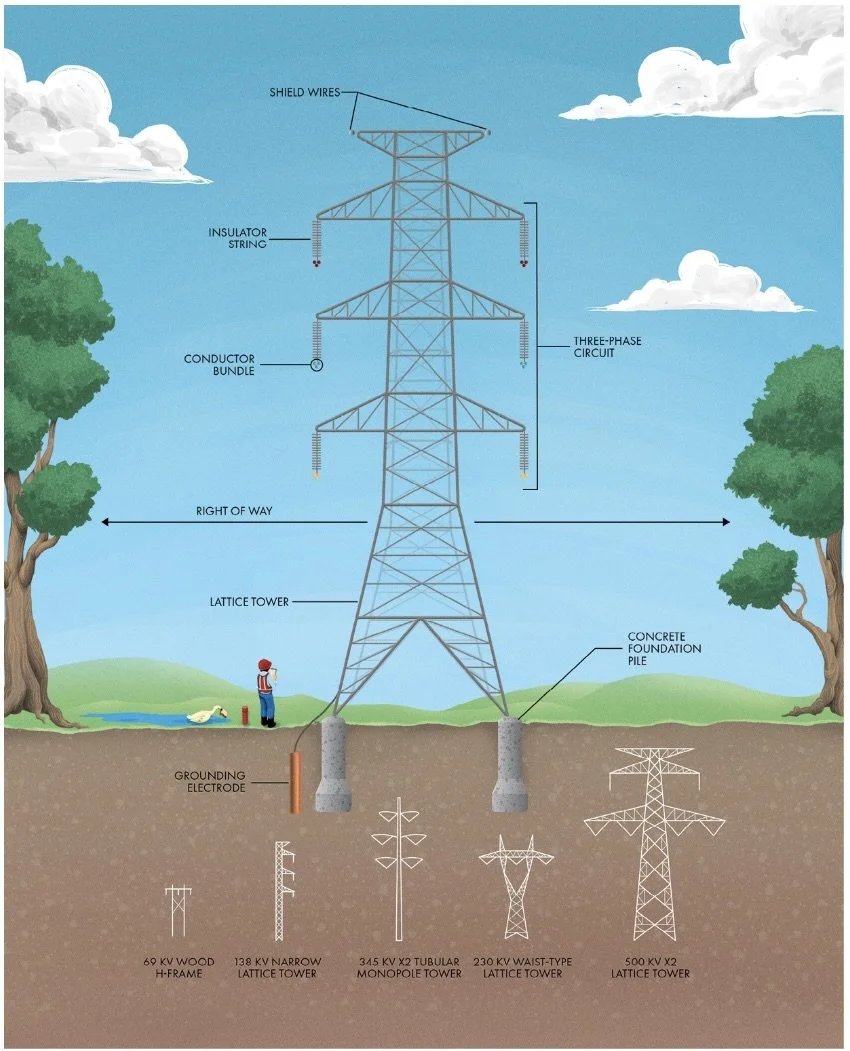
Transmission Line Components
Conductors are almost always made from many individual strands of Al. Al is a great choice because it’s lightweight, doesn’t easily corrode, and offers low resistance to electrical current. Al cables are often reinforced with steel or C fibers for extra strength. Most of the insulation for HV lines comes from air gaps- large amounts of space between the energized lines and anything that might serve as a path to ground.
Conductors are connected to each tower through long insulator strings. Traditionally, insulators have been made from a string of ceramic discs (usually glass or porcelain). The discs lengthen the flow path of electricity leakage if the insulator gets wet or dirty, reducing how much power can escape. These discs are also somewhat standardized in size, so counting them provides an easy way to roughly guess a line’s voltage: multiply the number of discs by 15 kilovolts (kV). Nonceramic insulators are becoming more popular, including those made using Si rubber and reinforced polymers.
Power on the lines can be lost to corona discharge, an effect created from ionization of the air surrounding the conductors. Listen closely and you can occasionally hear the corona discharge as a sizzling sound, particularly on dewy mornings, during stormy weather, or in high altitudes where atmospheric pressure is low.
One way to estimate the voltage of a transmission line is to count the number of bundled conductors for each phase. Lines below 220 kV commonly use only 1-2 conductors, and lines above 500 kV often have 3+.
Dampers are often installed to absorb wind energy and reduce long-term damage to the wires.
High-voltage DC (HVDC) lines have many benefits over AC. AC power must “charge up” the line each time the current changes direction, which requires a lot of extra power. HVDC lines aren’t affected by this effect (called capacitance) and thus can be more efficient. HVDC lines are also used as connections between separate power grids where the alternating currents may not be synchronized. HVDC transmission lines use incredible voltages (up to 1100 kV), but they are still relatively rare, especially in North America.
Substations
Substation: An integral part of the electrical grid that serves myriad purposes including monitoring the grid’s performance, changing between different voltage levels, and providing protection against faults. The most commonly seen substation around cities are step-down facilities that convert HV transmission to a lower, safer voltage for distribution within populated areas. Substations often serve as the termination points of many transmission lines. HV lines enter the substation through a support structure called a dead-end that provides support and spacing. These are the only locations where very HV lines drop from their safe heights down to ground level, so extra precaution is required.
The heart of a substation and the primary connection between all the various devices and equipment in a substation is the bus, a set of three parallel conductors (one for each phase).
Substations have a HV side and a LV side, separated by the power transformers.
At step-down facilities, power leaves the substation as individual circuits called feeders. Each feeder has its own circuit breaker, allowing smaller groups of customers to be isolated from the grid in the event of a fault.
As with transmission lines, lightning poses a severe threat to substations. Static poles and lightning rods poke into the air to capture strikes and shunt them directly to ground, protecting costly equipment from surges.
All substations are built with a ground grid, a series of interconnected copper wires buried below the surface. In the event of a fault or short circuit, the substation needs to be able to sink lots of current into the ground through this grid to trip the breakers as quickly as possible. This grounding grid also makes sure that the entire substation and all its equipment are kept at the same voltage level, called an equipotential.
Much of the equipment used in outdoor substations is called air insulated switchgear because it uses ambient air and spacing to prevent HV arcs from forming between energized components.
1 Electrical Substation
Substation Equipment
Substations step up or down voltage between the more efficient (but more dangerous) HV from transmission lines and the lower (and easier to insulate, although still quite dangerous) voltage for the smaller lines within urban areas. This conversion is done using a power transformer, a device that relies on the AC of the grid to function with no moving parts by taking advantage of electromagnetism.
Transformer: Consists of two adjacent coils of wire. The AC of the input electricity generates magnetic fields that are focused and directed by a laminated core consisting of many thin sheets of iron. These magnetic fields couple to the adjacent coil, inducing a voltage in the output wires. The voltage out of the transformer is proportional to the number of loops in each coil. The insulators guiding conductors into and out of the transformer are called bushings. They support the energized lines as they pass through the metal case into the transformer, protecting against short circuits.
Circuit breakers provide the means to stop the flow of electricity, allowing faults to be isolated from the rest of the system. They not only protect the other equipment on the grid, but also make problems easy to find and repair. Even if you create a break in the line to disconnect it, electricity can continue flowing through the air in a phenomenon known as an arc. All breakers are connected to devices called relays that can automatically trigger during a fault condition.
Relays: Monitor the voltage, current, frequency, and other parameters on the grid to identify problems and trigger the breakers.
Special transformers called instrument transformers convert the HV and currents on the conductors to smaller, safer levels that can be sent to the relays.
1 Transformers and Circuit Breakers
Typical Utility Pole
If transmission lines are electrical highways, distribution lines are the residential streets.
Typical utility poles start at a substation where individual power lines (‘feeders’) fan out to connect to residential, commercial, and industrial customers.
Most utility poles have their own earth wire running down the pole attached to an electrode driven into the ground. This wire provides a safe path for any stray currents…The primary distribution conductors (or lines) you see at the top of utility poles are considered medium voltage and usually range from 4 kV to 25 kV. Energized lines are easy to identify because they are supported by insulators.
Distribution transformers reduce the voltage to its final level—often called mains or secondary voltage—for use by regular customers. The secondary service drops that connect each customer to the grid are located below the primary conductors. For the safety of workers, the energized lines are always at the top of the poles with space to work between them and other telecommunication lines (such as cable, telephone, and fiber-optics).
One major difference from transmission lines is that the number of conductors on the distribution grid increases from three to four. This is due to how electrical demands are distributed between each of the grid’s three phases. All electrical circuits are loops, so they require two lines: one to supply the current and one to return it to the source. On HV transmission lines, the electricity usage between each of the three phases is perfectly balanced, eliminating the need for a separate return path for electricity. Each pair of phases serves as a source and a return path at the same time. However, on the distribution side, it’s not always so simple. Many electrical consumers (including most residential homes) make use of only a single phase. In fact, on the distribution grid, the three phases are often split from one another to service different areas entirely. Look around some residential neighborhoods and you may see many poles with only a single primary conductor and no cross arm.
Voltage regulators are devices with multiple taps that can make small adjustments to the distribution voltage.
Electrical Distribution Equipment
A distribution transformer is needed to step down the voltage to the level generally used in buildings by lights, appliances, and other devices. These transformers often appear as gray canisters just below the conductors on utility poles. They are filled with oil, just like the transformers at substations, and work in almost the same way.
The output of distribution transformer coils uses a split-phase design. In this configuration, two energized (or hot) lines are supplied to the customer with one neutral conductor connected to ground. One of the energized lines is inverted from the other. In this way, smaller appliances can use the line-to-neutral voltage, about 120 V nominal (170 V peak) in most of North America. Devices requiring more power (such as heaters, air conditioners, and clothes dryers) can be connected between the two energized lines, receiving double the voltage.
The fused cutout serves as both a circuit breaker and an isolation switch. The fuse automatically protects a service transformer from short circuits and voltage surges. If the current in the fuse gets too high, the element inside melts, breaking the circuit and disengaging a latch, allowing the fuse door to swing down.
Reclosers, which are usually housed in small cylindrical or rectangular canisters. Reclosers open when a fault is detected, then close again to test whether the fault has cleared. If you ever lose and regain electricity in a short period of time, a recloser is probably why.
In the urban core of many cities, you’ll hardly see any overhead lines at all. Instead, power is run in ducts below the ground.
___________________________________________________________________________
Ch 2 Communications
Overhead Telecommunications
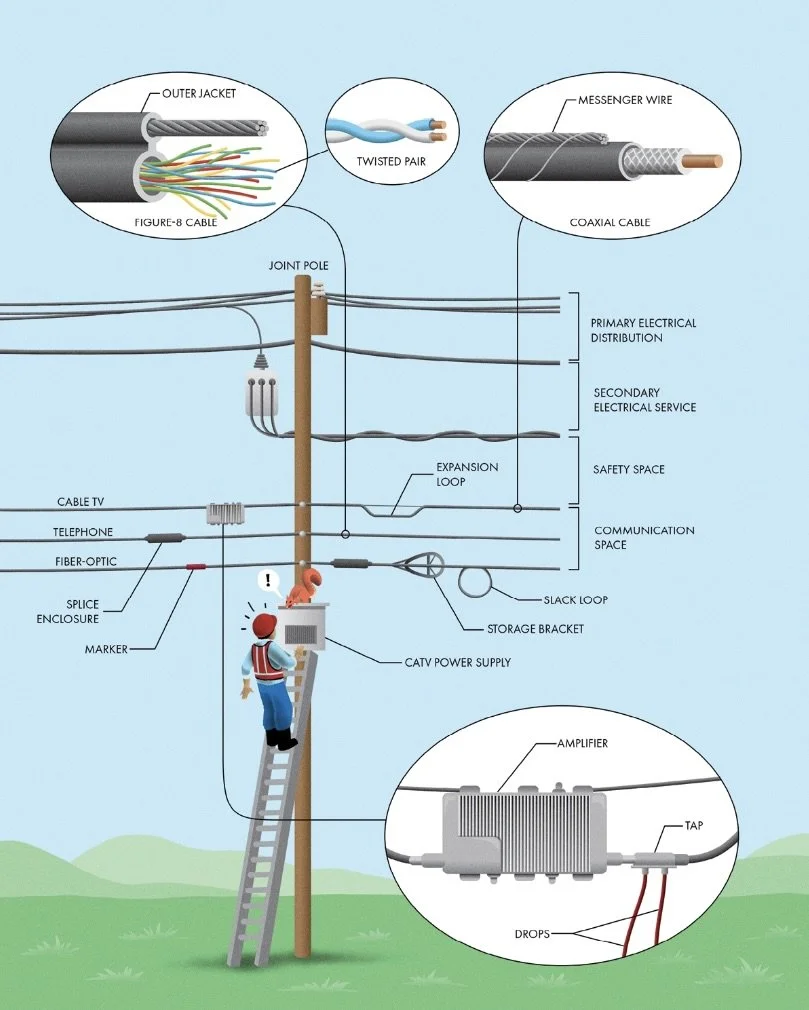
Only three types of transmitter make up the preponderance of what you can observe on a standard pole: telephone, coaxial cable TV, and fiber-optic lines.
Although the network of copper lines that make up the plain-old telephone service (POTS) are quickly being phased out, they still can be seen on poles around the world. Since 1876, we’ve been transmitting voice signals along dedicated circuits of copper wire, and it’s still the simplest way for a home or business to connect to the telephone network in many places. Each landline consists of a twisted pair of thin copper wires. Since every household and business can have its own direct lines to the local telephone exchange, the cables can grow quite large, sometimes containing hundreds or thousands of pairs. The lines join together into larger and larger cables at splices, easily visible by the boxy black splice enclosures seen near poles.
The Cable TV Network (‘CATV’) network begins at a central location, which is called the head-end. From there, the signals are distributed mostly using coaxial cable, named because the inner conductor and surrounding metal shield are concentric around a common axis. These cables can carry HF radio signals with very low losses or issues with interference because of the shielding effect of the outer conductor. They start as large trunks that feed multiple distribution lines. Amplifiers (‘line extenders’ and recognizable by their heat-dissipating fins) are spaced along trunks to boost the signal. A CATV power supply provides the necessary power for all the amplifiers within a large radius. Taps in the distribution lines allow the connection of drops, which provide service to each individual customer.
Both cable and telephone providers now often use fiber-optic cables in combination with copper wires or coaxial cables to distribute higher quality and more reliable signals. These cables utilize bundles of glass or plastic fibers to transmit signals as pulses of light. Fiber-optic signals can travel huge distances with very little loss because they are immune to electromagnetic interference. The outside of the cable sometimes includes an orange or yellow marker or overwrap, making it easy to distinguish from telephone or CATV.
2 Telecommunications Lines
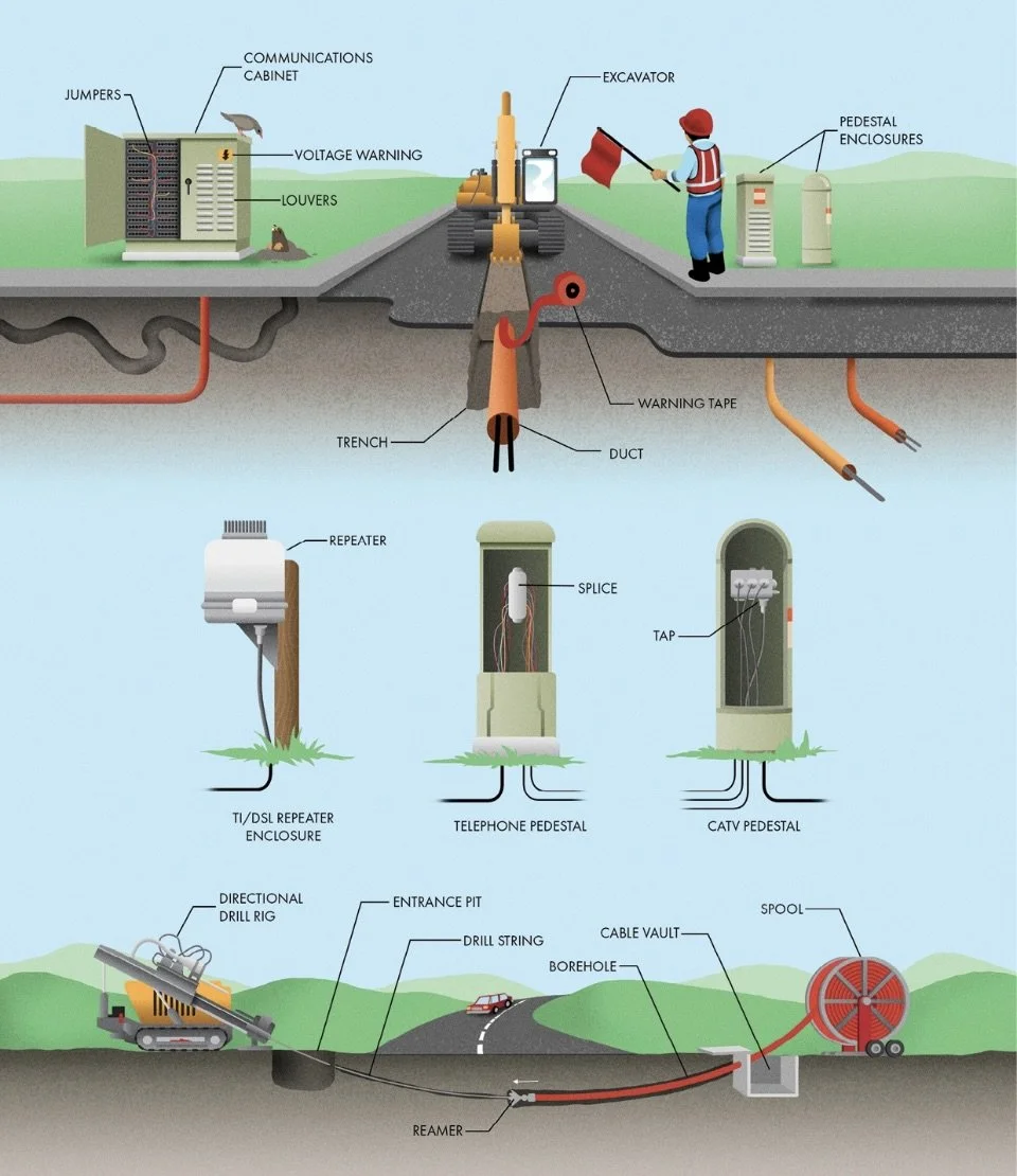
Underground Telecommunications
These ubiquitous housings are usually termination points, providing the connection between a larger distribution line and smaller cables that fan out toward customers for CATV, telephone, or other telecommunication services.
2 Underground Telecommunications
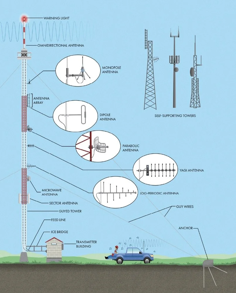
Radio Antenna Towers
Radio signals generally can’t reach beyond the horizon, which is why many antennas are mounted at the tops of gigantic towers (‘masts’).
Radio antenna towers can take many forms, but there are two main categories of structure (not including the spires atop tall buildings): self-supporting and guyed. Self-supporting towers are designed to be freestanding and stable against the wind entirely on their own.
Guyed towers usually consist of a slender lattice structure supported by multiple steel cables (the guy wires).
For AM radio stations, the tower itself is the antenna and there may be a tuning hut at the tower base that houses equipment needed to efficiently transfer power from the transmitter to the tower. For FM and TV stations, the feed line (also called a transmission line) carries the signal from the transmitter up to the antenna, which is attached to the tower structure.
The antenna is the device that radiates the signal as electromagnetic waves.
Omnidirectional Antennas: An antenna that transmits radio waves in all directions equally and often have a cylindrical shape. They include monopole antennas, straight conductive elements that require a ground plane (sometimes the ground itself and sometimes consisting of radial, horizontal conductors).
Dipole Antennas: A kind of omnidirectional antenna that consist of two identical radiating elements, one above the other.
Directional Antennas: Antennas that focus radio waves in a specific direction.
Parabolic Antennas: Antennas with a solid or gridded wire dish to reflect and focus radio waves.
Yagi Antenna: An antenna that use a single energized dipole and several non-energized elements to focus the waves in the desired direction. Similar in appearance, log-periodic antennas use a series of dipoles, each of a slightly different length to send or receive a wide range of radio frequencies.
2 Antenna Towers
Satellite Communications
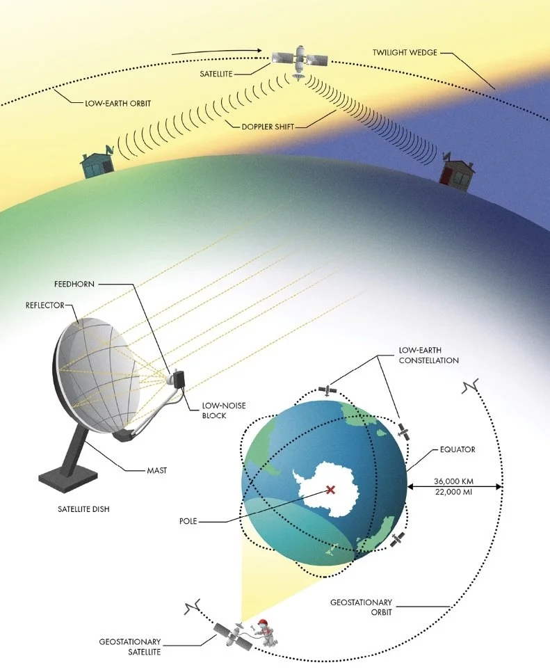
We use satellites for a wide variety of communications, including radio, television, internet, telephone, navigation, weather, environmental monitoring, and so much more. Satellites used for communications are essentially relays, receiving signals from one location on the ground and amplifying and redirecting them back to somewhere else on Earth.
The speed at which a satellite orbits is directly related to its altitude. The higher the orbit, the longer it takes to go around. Satellites in low-Earth orbit circle the globe many times per day, so they are overhead at a specific location for only short periods of time. A group of satellites in overlapping orbits, called a constellation, is required to maintain continuous service. Each satellite is strategically placed so that any location on the ground has at least one satellite within line of sight at all times. Low-Earth orbiting satellites require less power to transmit and receive, and communications experience less delay, since they are closer to the Earth. Low-Earth satellites do have to account for Doppler shift. Because the satellites move so quickly compared to an observer on Earth, the radio waves compress while moving toward an antenna and stretch out as they pass by overhead, complicating the job of receiving and decoding the signals.
At an altitude of approximately 36,000 km, the orbital period of a satellite is 24 hrs. A satellite at this altitude around earth’s equator is in a geostationary orbit because it remains in a fixed position in the sky as the Earth rotates. One limitation of geostationary satellites is that they are constrained to a single ring (called the Clarke Belt) above the Earth’s equator. To avoid satellites interfering with each other’s signals, the international telecommunications community agreed to designate individual locations (called slots) around this ring like parcels of real estate. The geostationary ring is so congested that it has a waiting list. Once a satellite has reached the end of its useful life, it must move out of its slot so that a replacement or a new satellite on the waiting list can take its place. The other disadvantage with geostationary satellites is their large distance from the Earth. Sending and receiving radio signals across this great expanse is a major challenge. The antennas used to overcome this distance are instantly recognizable. A satellite dish uses a curved reflector to gather the faint radio signals and focus them into the feedhorn. This metal cone transitions the waves into the low-noise block, the heart of the satellite antenna that includes electronic circuitry to perform two primary functions. First, it amplifies the weak radio signal to a more usable level. Second, it takes the HF signal used for long-distance wireless transmission and down-converts it to a LF that can travel efficiently through a cable.
2 Satellite Communications
Cellular Communications
Within only a narrow range of frequencies, wireless carriers have innovated ways to connect anyone with a mobile device to both the telephone network and the internet. The fundamental innovation making this possible is the subdivision of large service areas into smaller cells—hence the name, cellular communications.
Base Station (‘Cell Site’): A station with the infrastructure needed to provide service to one or more wireless cells, usually including a tower, antennas, amplifiers, signal processing equipment, a backhaul connection to the network, and sometimes batteries or a backup generator for power outages.
Rectangular sector antennas are used to send and receive the signals used by mobile devices. These antennas are highly directional to maintain clear boundaries between cells, usually targeting a 120-degree swath of territory. The triangular platforms atop some towers allow for antennas to service three cells from one station, and each antenna is carefully aimed to avoid interference with neighboring cells.
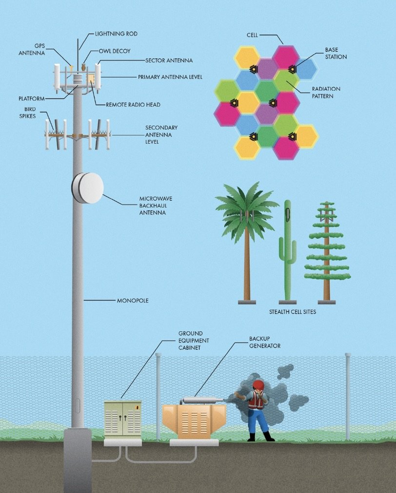
2 Cell Site Base Station
___________________________________________________________________________
Ch 3 Roadways
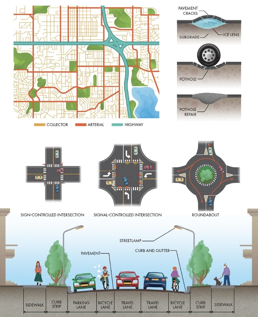
Urban Arterial and Collector Roads
The formation of a pothole happens in steps, the first of which is deterioration of the surface pavement. They might seem innocuous, but cracks are critical flaws in a pavement system because they let in water. Soil below the pavement can become waterlogged from precipitation, softening and weakening the subgrade. Water below the roadway can also freeze and grow into a formation called an ice lens. Water expands when it freezes, and it does so with tremendous force, separating the subgrade and pavement. When those lenses thaw out, the ice that was supporting the pavement recedes, creating voids. Every time a tire hits this soft area, it pushes some of the water and underlying soil back out of the pavement. It’s a slow process at first, but every little bit of subgrade eroded from beneath the pavement means less support, and less support means more volume below the pavement for water to be pumped in and out by traffic. Eventually, the pavement loses enough support that it fails, breaking off and creating a pothole.
Pedestrian and Bicycle Infrastructure
Sidewalks are designed with control joints to constrain the cracks’ location to a regular pattern by artificially weakening the concrete. These induced cracks are preferential to the unsightly random arrangement that would otherwise occur. Also, concrete shrinks and expands according to temperature. On small structures, this may be imperceptible, but for long shapes (like sidewalks), the thermal movement can add up. Occasional spaces, called expansion joints, are left in the concrete to prevent sidewalks from buckling or having significant gaps. The joints are typically filled with wood, cork, or rubber to allow for movement over time.
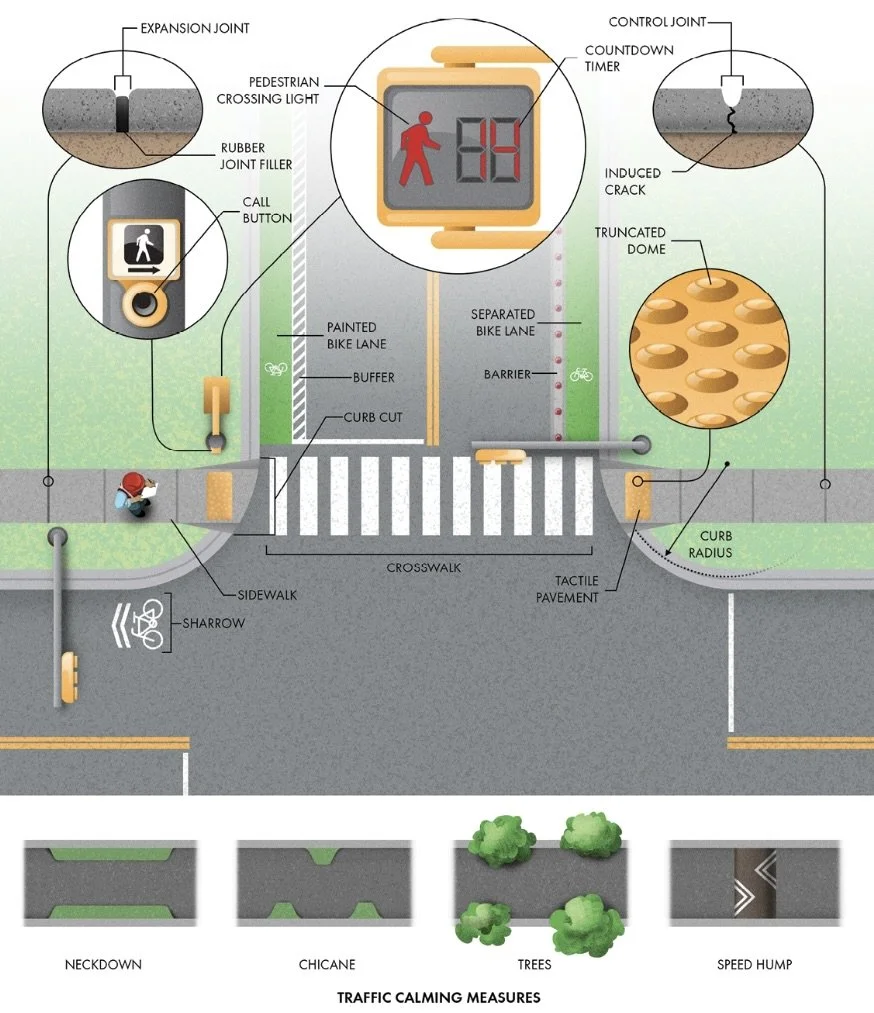
3 Crosswalks
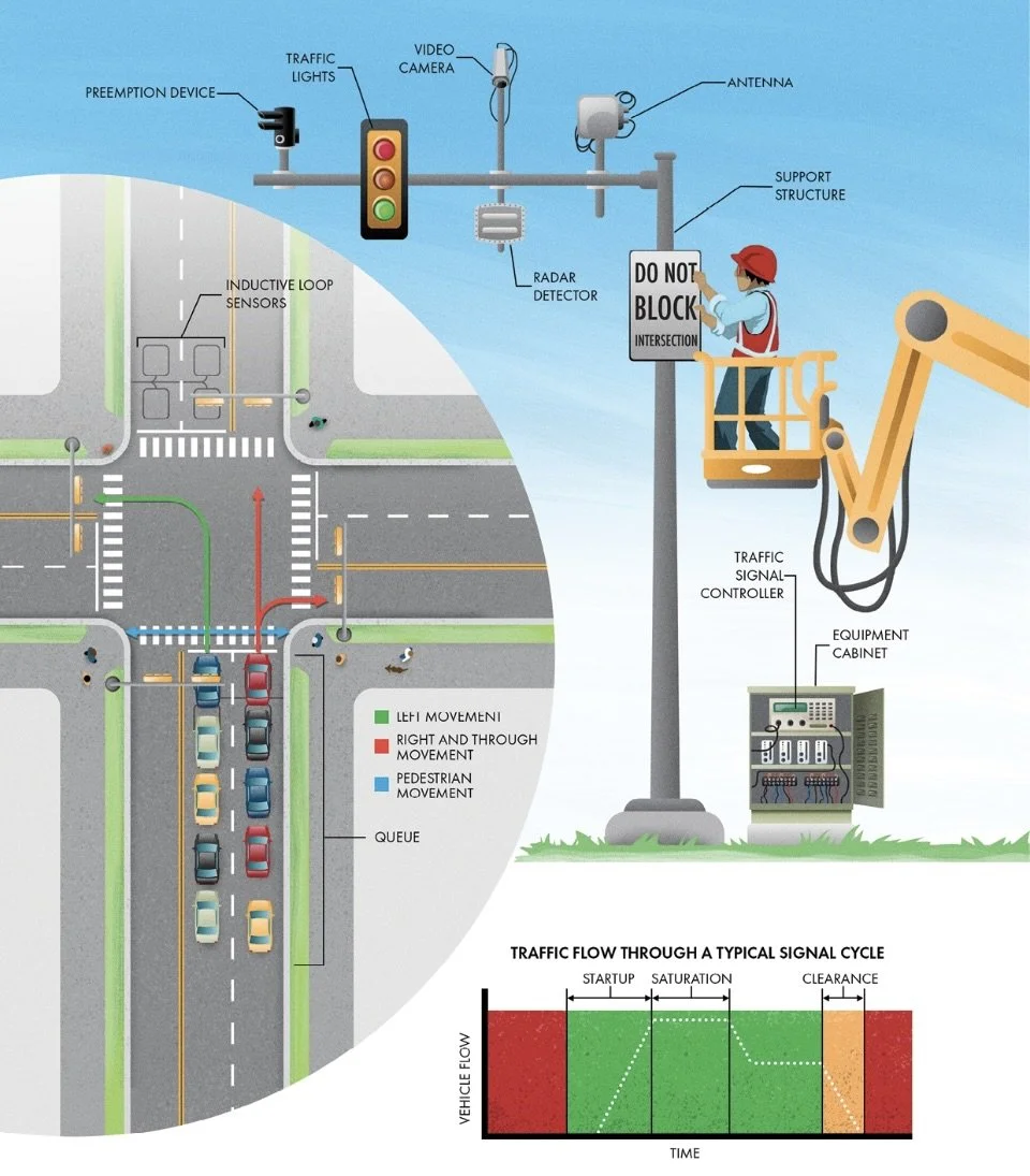
Traffic Signals
Traffic cycles include startup and clearance times. The duration of the amber light is usually set to around 1 sec per 10 mph on the speed limit.
In most places in North America, you are allowed to enter an intersection for the entire duration of a yellow light, which means there needs to be a time when all phases have a red light to allow the junction to clear. This clearance interval is usually about one second.
Actuated Signal Control: Traffic lights that can receive input from the outside to adjust timing and phase sequence on the fly. Actuated signals rely on data from traffic-detection systems that can be video cameras, radar detectors, or inductive loop sensors embedded into the road surface. These latter sensors are essentially large metal detectors that can measure whether a car or truck is present. Whatever the type of sensor, they all feed data into an equipment cabinet located nearby. You’ve probably seen hundreds of these cabinets without realizing their purpose. Inside this cabinet is a traffic signal controller, a simple computer programmed with logic to determine when and how long each phase will last based on the information from the detectors. Actuated control gives a traffic signal much more flexibility to handle variations in traffic load.
Actuated control can help prioritize emergency and public transportation vehicles equipped with specialized transmitters. Infrared or acoustic preemption devices communicate with transmitters on each prioritized vehicle to send the signal controller a call for green.
Signal Coordination: Traffic lights work in synchronization with each other and are employed on long corridors with small but frequent cross streets. The signals on the major road are timed so that a large group of vehicles, called a platoon by traffic engineers, can make it some or all of the way through the corridor without interruption.
Adaptive Signal Control Technologies: The coordination of most or all of the signals within a traffic network. In adaptive systems, rather than individual groups of lights, all the information from detectors is fed into a centralized system (often wirelessly with antennas at each signal) that can use advanced algorithms to optimize traffic flow throughout the city.
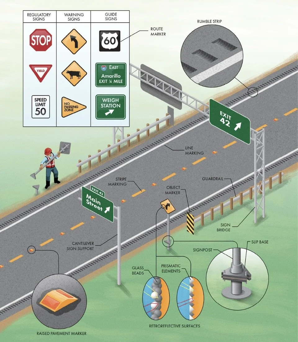
Traffic Signs and Markings
Traffic Control Devices: Signs and markings used to regulate, warn, or guide traffic on roadways.
Three major categories of signs (along with many minor types) are used on roadways: regulatory, warning, and guide signs.
Regulatory Signs: Inform road users of traffic laws and include speed limit, stop, and yield signs. They mostly use a combination of black, white, and red colors.
Warning Signs: Alert road users to hazards or unexpected conditions. They are almost always yellow diamonds with black writing. Object markers are another type of warning sign to mark obstructions in the roadway or alongside it using diagonal yellow and black stripes.
Guide Signs: Inform road users of helpful information for navigation and direct them along their way, and they’re almost always green with a white border and message. Route markers are another type of guide sign. They use distinctive shapes (often shields) and colors to differentiate road classifications.
When carried by a single vertical member, they are called cantilever sign supports. These extend only so far because the load is unbalanced. For wider roadways, the supports are held on both sides by a structure called a sign bridge.
Almost all signs and roadway markings are retroreflective, meaning they reflect light back toward its source in the same direction as it came. Retroreflective surfaces take advantage of headlights, bouncing their light directly back toward the vehicle and driver inside. Signs are surfaced with plastic sheeting embedded with glass beads or prismatic elements. Retroreflective glass beads are also embedded into the markings on roadway surfaces, making them more visible to vehicles with their headlights on.
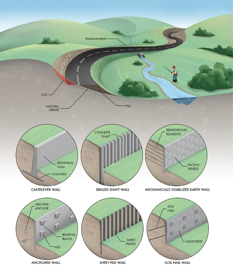
Highway Earthwork and Retaining Walls
Earthwork: All the ways we use to modify the ground’s shape and structure.
Areas above a proposed roadway need to be excavated away, also known as areas of cut. Excavation is necessary when the final level will be lower than the surrounding terrain, such as through a steep hillside. Areas below the proposed road need to be raised with fill, such as when passing over a stream or on the approaches to a bridge. Larger areas of fill are often called embankments. Cuts and fills are the most fundamental elements of any earthwork project.
3 Highway Earthworks
Typical Highway Section
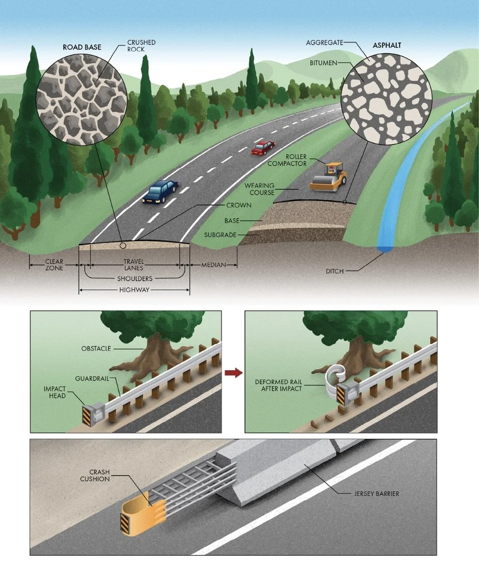
Roads are built in layers, sometimes called courses, to make them durable and long-lasting.
Before any new roadway can be installed, some earthwork is required to smooth the surface of the earth. The layer of existing soil upon which a road is constructed is called the subgrade, and it’s not always well-suited to withstand the tremendous and frequent loads from vehicular traffic. Instead, one or more courses of road base are placed and compacted on top of the subgrade, often made from crushed rock.
The top layer of pavement is the wearing course because it’s the one exposed to the controlled chaos of constant motor vehicle traffic. Concrete is occasionally used as the wearing course for major highways because it is exceptionally hard and durable. Concrete consists of cement, rocks (‘aggregate’), and water, and it can withstand huge volumes of heavy truck traffic better than any other pavement. But concrete has some disadvantages, too. It is expensive to install. It’s hard to repair because it takes a long time to cure, extending the duration of road and lane closures. And it can also be too slick when wet, so it must be grooved for traction with tires. That’s why, instead of concrete, most roadways are paved using asphalt.
Asphalt pavement has only two primary ingredients: aggregate and bitumen, a thick, sticky binder material from the refinement of crude oil. Asphalt is heated into a workable mix, placed atop the base course, and then compacted into place with heavy rollers.
Longitudinal barriers keep vehicles from leaving the roadway when a dangerous obstacle or drop-off is present.
Jersey barriers are made of concrete. Their shape allows a tire to ride up the side, often redirecting the vehicle without causing significant damage.
Rigid barriers often include a crash cushion at their ends. There are a wide variety of designs, but the most common feature barrels filled with sand or crushable steel components that can absorb the energy of a collision, significantly reducing the severity.
A typical paving “train” consists of a milling machine to remove the old asphalt, a recycling unit to warm and mix it with additives, a paver to place the rejuvenated asphalt, and compactors to compress it into place.
3 Highway Sections
Typical Highway Layout
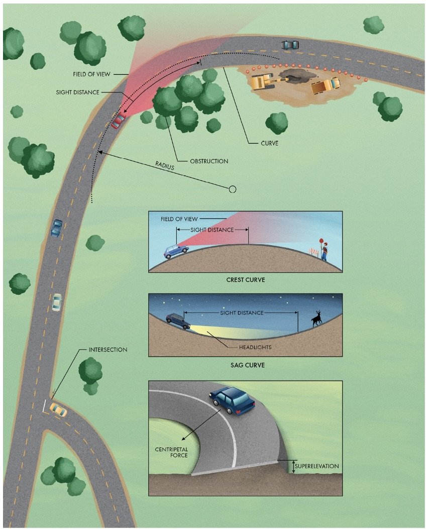
Layout: The roadway as it unfolds as you drive along.
Horizontal Layout: A highway’s alignment as it appears when looking from above.
Sight Distance: The length of the roadway visible to the driver at any given point in time.
3 Highway Layout
Interchanges
Although strong when compressed, concrete quickly fails when subjected to tension (pulling) forces.
Reinforcement within concrete creates a composite material, with the concrete providing strength against compressive stress while the reinforcement provides strength against tensile stress. For bridge beams, this reinforcement is often pre-stressed. The steel bars are stretched and held taut while the wet concrete is cast into a mold. Once the concrete hardens, the tension in the steel compresses it tightly like a rubber band, making the beams stiffer and less prone to cracking.
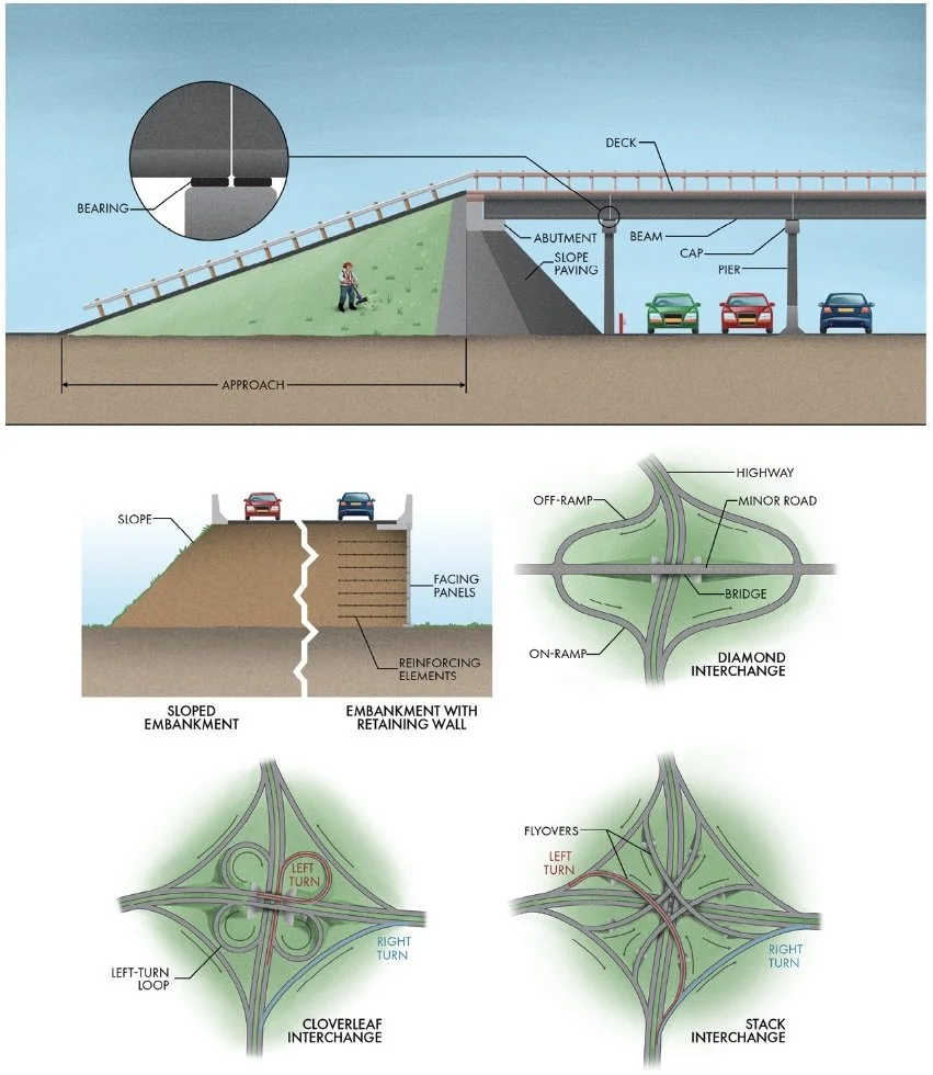
3 Highway Interchanges
___________________________________________________________________________
Ch 4 Bridges and Tunnels
Types of Bridges
Beam Bridge: A bridge that consists of one or more beams (‘girders’) resting on piers or abutments below.
Cantilever Bridge: A bridge that uses beams or trusses that project horizontally from their supports, moving most of the weight above the supports rather than in the center of the span.
Cable-Stayed Bridges: Bridges that support the bridge deck from above through cables attached to tall towers. The cables (also called stays) form a fan pattern, giving this type of bridge its unique appearance.
Suspension Bridge: A bridge that uses two massive main cables to dangle the road deck below with vertical hangers.
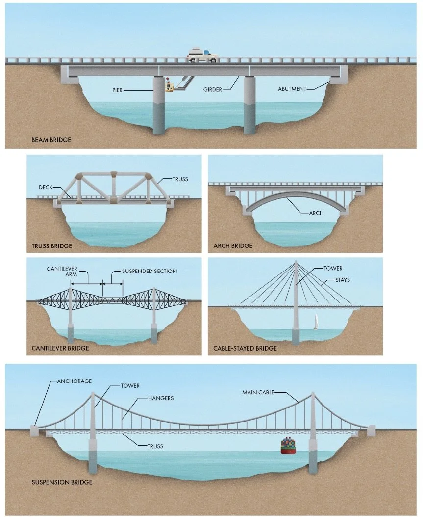
4 Bridges
Typical Bridge Section
The superstructure carries the traffic loads across each span and the substructure transfers the weight of the superstructure into the foundation. The deck is the surface of a bridge upon which vehicles travel. Most bridges will have some type of beams, or girders, to support the deck, depending on the design.
Girders experience the most significant forces along their upper and lower extremities. Generally, the top of the beam undergoes compression and the bottom experiences tension, so most girders are shaped like a capital “I” to have more material in the flanges, with a narrow web in the center where forces are not so significant.
The substructure consists of vertical elements that carry the loads from the girders, deck, trusses, cables, and hangers and transfer them to the underlying ground.
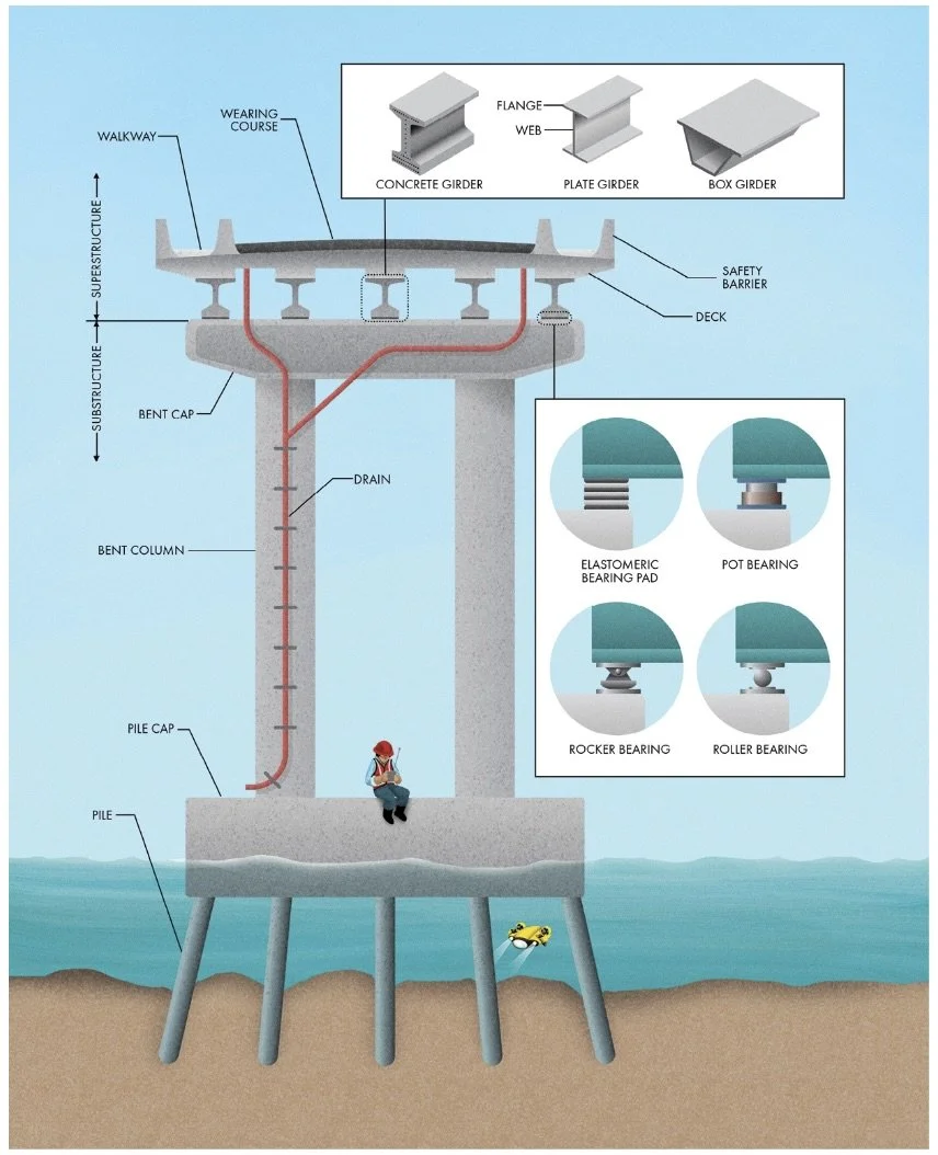
4 Bridge Super and Substructures
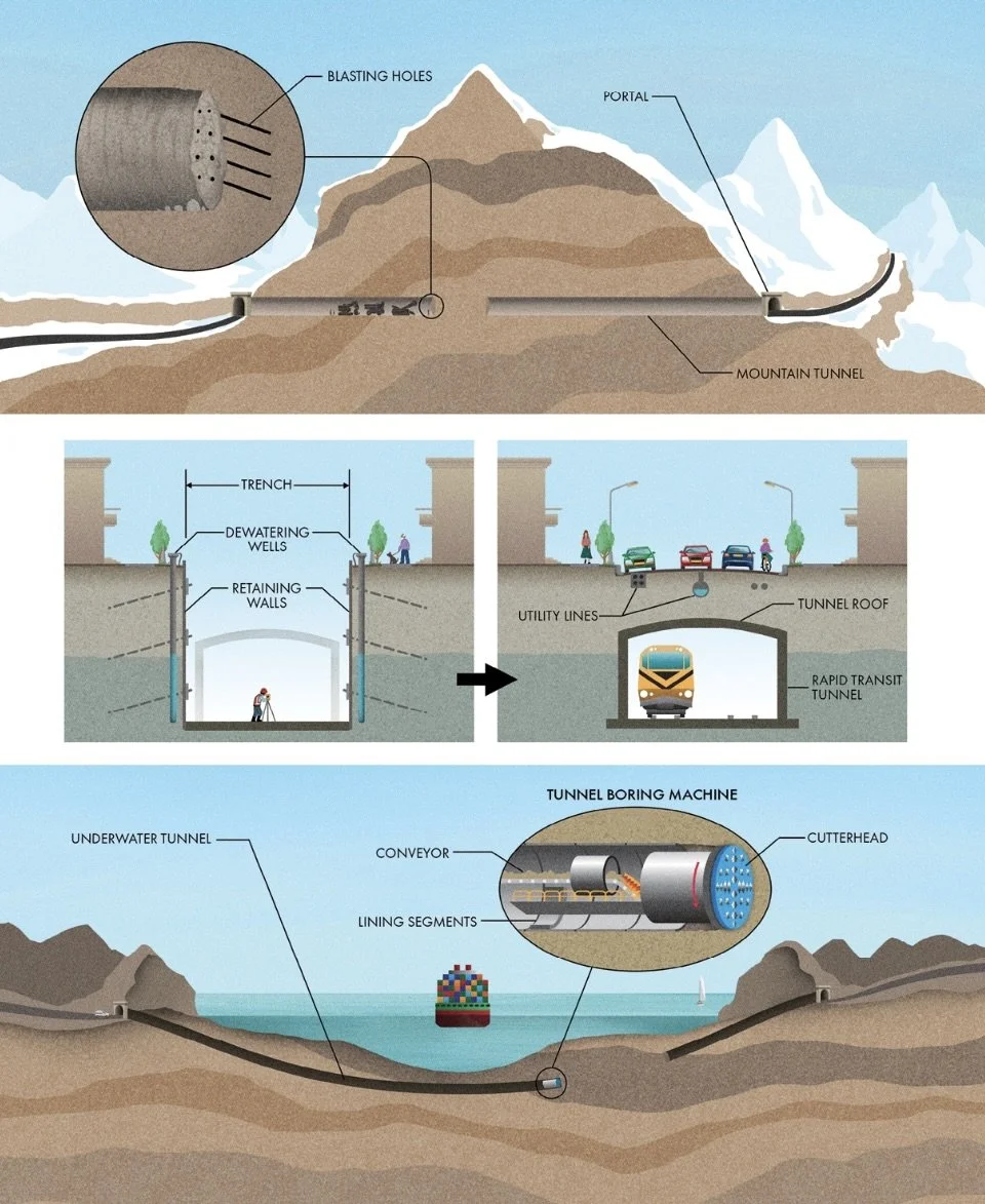
Overview of Tunnels
Cut and cover tunnels are made by digging a trench, constructing the tunnel, and then filling it over with soil.
Boring a tunnel follows a few main steps: excavate and remove the soil or rock, install supports to hold back the surrounding earth and water, then complete the tunnel features.
Tunnel Boring Machine (TBM): Massive pieces of equipment that act like giant drills, using a rotating cutterhead to chew through the rock and soil. TBMs also include conveyors to remove the spoils as they are excavated and equipment to install concrete lining segments that support the tunnel walls and roof.
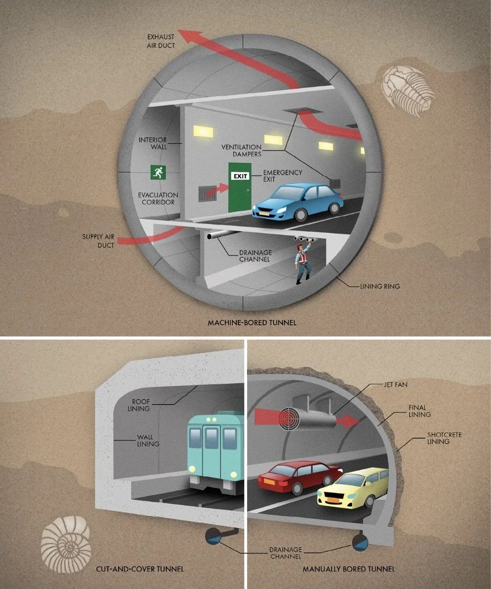
4 Tunnel Types
Tunnel Cross Section
Most tunnels are installed with a lining to resist the pressure from the ground, hold the passageway open against collapse, and minimizing the infiltration of groundwater.
Manually bored tunnels are often lined using concrete sprayed on the walls, called shotcrete, to provide the initial support. This layer helps hold the soil and rock together while stresses redistribute after excavation. A final lining of steel or concrete is added later. In urban cut-and-cover tunnels, the lining usually consists of reinforced concrete cast in place. The falsework and reinforcing steel are erected first, and then concrete is pumped or poured into the forms to harden. Once it has cured, the formwork is removed, and the soil around the tunnel walls and roof can be backfilled. For machine-bored tunnels, the lining usually consists of concrete rings. Each ring is made from precast segments and delivered to the tunnel face, ready to be lifted into place. The segments include a gasket to seal out groundwater and use tapered geometry to lock tightly together when installed.
Many tunnels are too deep to drain freely. In this case, they are equipped with small reservoirs at low spots called sumps. When the sump fills with water, a switch turns on a pump that delivers the tunnel drainage to a sewer or outfall.
Many tunnels work like simple pipes with fresh air entering one portal and exhaust air leaving the opposite side. This scheme is known as longitudinal ventilation. It is accomplished using jet fans mounted to the ceiling that force the air inside the tunnel to keep moving.
Transverse ventilation- where the air is supplied or exhausted at discrete locations throughout the tunnel’s length. Transverse ventilation requires ducts to deliver fresh air or remove exhaust from each damper in the tunnel. Two ducts are necessary for a fully transverse system: one for supply air and one for exhaust.
4 Tunnels
___________________________________________________________________________
Ch 5 Railways
Railways take advantage of two features to provide rapid and efficient transportation of people and goods. First, the steel wheels on steel rails waste little energy to friction (especially compared to rubber tires on asphalt). Locomotives may look huge, but their engines are almost trivial compared to the enormous weight they move.
Railroad Tracks
The force required to move a train forward is transferred into the rail through friction with the driven wheels of the locomotive. Incredibly, the contact patch between each wheel and the rail is only the size of a small coin.
Historically, lengths of rail were bolted together using fishplates. The joint between each section creates the iconic click-clack sound as the wheels of the train pass over the small gap. These small but frequent discontinuities generate wear and tear on the railway vehicles (‘rolling stock’) and are uncomfortable for passengers. Most modern tracks use welded rails to create continuous stretches of smooth-running track with no joints.
On scorching days, railways can buckle (‘sun kink’), creating the danger of a derailment. Rails are often warmed or stretched before installation to mitigate the possibility of buckling. This technique raises the neutral temperature of the rail so that hot days don’t overload it with thermal stress.
There are many ways to attach the rail to the horizontal ties (also called sleepers). Historically, a large steel spike with an offset head was hammered in place to secure each side of the rail. These spikes are still used on some railroads in the USA. More modern railways use one of many types of heavy-duty clips. In North America, ties are usually made from wood because of its abundance, but they can be made from concrete as well. Ties have two essential jobs: bear the weight of loads from the train traffic above and keep the two rails running with the correct space between (called the track gauge). Wooden ties often include a tie plate to distribute the concentrated force of the rail.
Railroad ties do not sit directly on the ground below the track, called the subgrade. The soils are rarely strong enough to bear the immense weight of train traffic. Instead, an embankment of loose rock called ballast is used to spread the load evenly to the underlying soil. Ballast is often made from crushed stone because the angular features help it interlock into a solid foundation. Not only does it distribute the vertical forces from the track, but ballast also provides horizontal support to each tie, helping resist buckling due to thermal stress and shifting from horizontal train forces around bends.
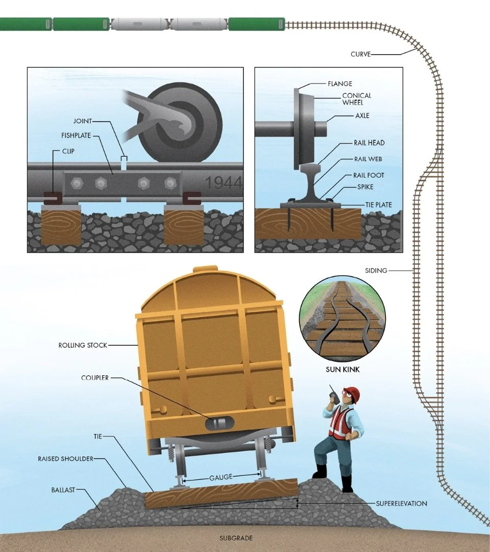
5 Railway Construction
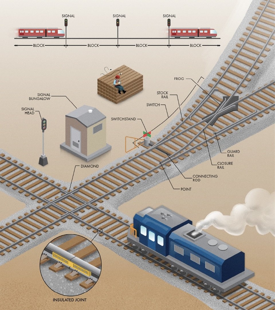
Switches and Signals
Most modern railway traffic control schemes are instead based on a block system. The tracks are subdivided into segments (‘blocks’), and trains are prevented from entering any specific block until it is free from obstructions. For non-signalized railways, traffic can be managed through warrants. A dispatcher provides a standardized authorization to the crew for specific train movements on the main tracks. However, most heavily trafficked lines use signals as the primary means of controlling traffic between blocks.
The simplest signals are those between blocks, which usually have a single signal head with three lights—green, yellow, and red—similar to those used at roadway intersections. A green light means the following blocks are clear and the train can continue at full speed. Yellow indicates that the next block is clear, but the one after is obstructed, and the next signal will indicate stop. A red light means the next block is occupied, and the train cannot proceed.
Some signals are controlled by a dispatcher, but many operate automatically using track circuits…The busiest companies use centralized traffic control offices that operate like air traffic controllers to coordinate the schedules and routing so that conflicts are avoided.
5 Railway Crossing Safety
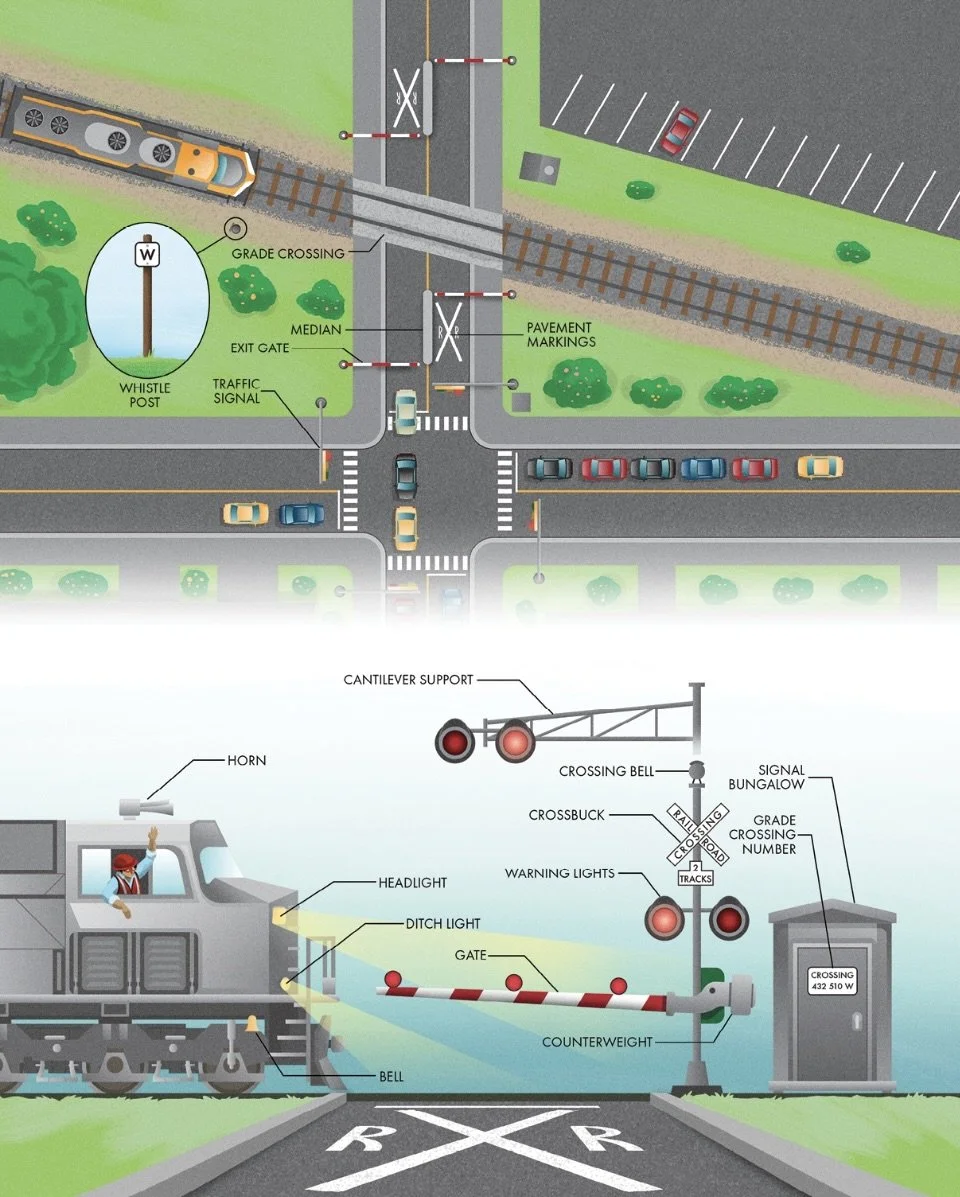
Grade Crossings
In many countries, grade crossings are assigned an identifier, called the grade crossing number, to simplify accident and malfunction reporting.
Passive Warning Devices: Warning devices that do not change when a train is approaching; include a stop or yield sign and a crossbuck, the international symbol for a railway crossing that consists of two slats in an X formation.
Active Warning Devices: Warning devices that provide a visual or audible notice that a train is approaching. They are usually triggered by a track circuit of the same kind used in automatic block signaling
Like railway signals, the relays, electronics, and batteries that control the automatic warning devices at grade crossings are hidden inside enclosures, often called signal bungalows. When a train approaches the intersection, a pair of red warning lights begins to flash, letting motorists know they need to stop…Many grade crossings include gates that drop across the oncoming lanes when a train crosses the roadway.
5 Railway Safety
Electrified Railways
Low-voltage DC cannot travel far in conductors without significant losses.
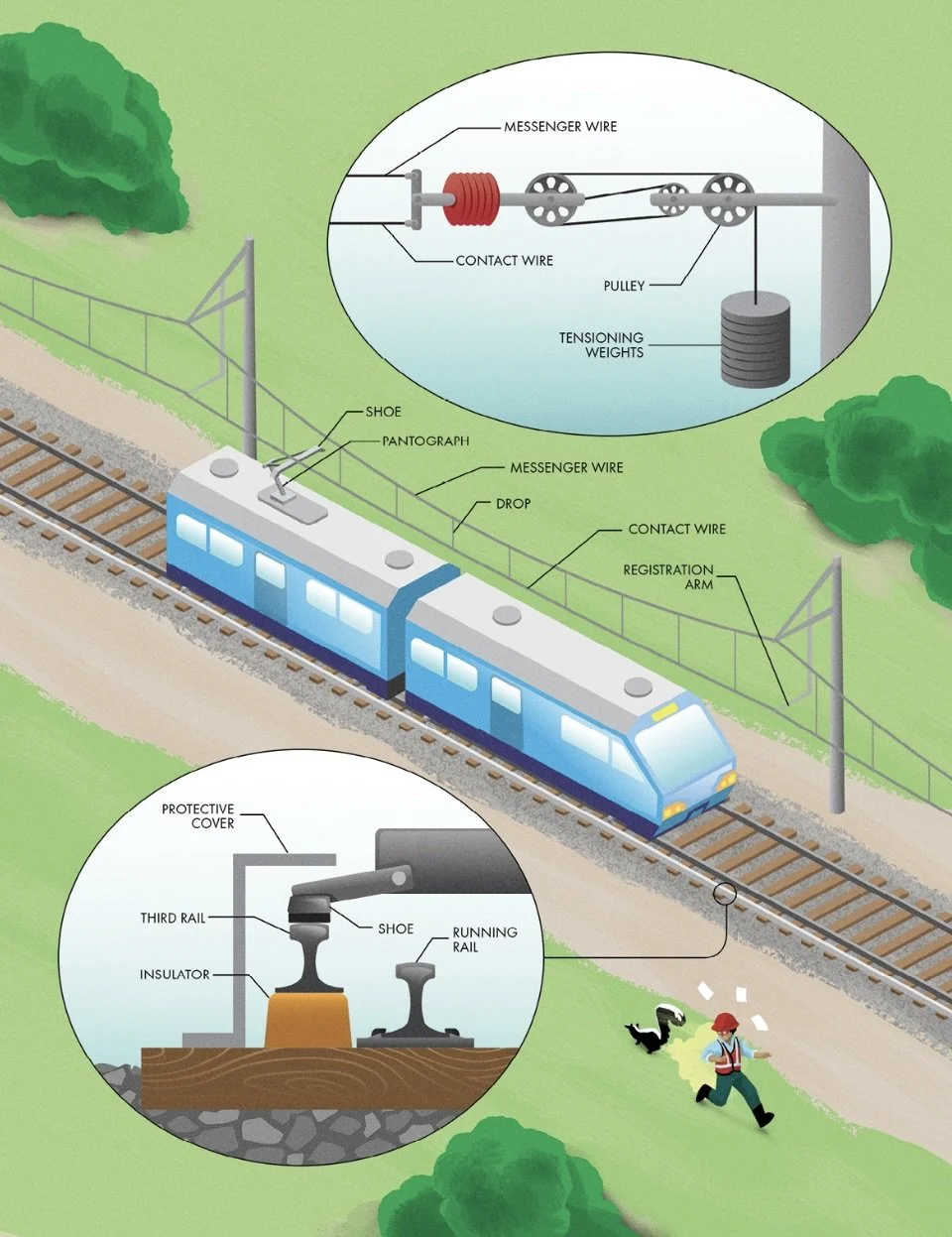
There are two primary ways to provide electric power to a train: a third rail or an overhead line. Third rail systems use an energized conductor that runs along the track parallel to the main rails. The energized rail sits atop insulators to keep it isolated from the ground. Trains are equipped with shoes that slide along the third rail to collect traction power…The other option for delivering electricity to trains is overhead.
Overhead lines are safer, and thus, most high-voltage systems are installed above the tracks. In this setup, a current collector sits atop the train. A few different devices can perform this task, but most modern trains employ a pantograph. They use spring-loaded arms to maintain contact between a replaceable graphite shoe and the overhead conductor.
An electric circuit requires a loop, so electrified railways need a second conductor to complete the connection. In most electrified railways, return current travels in the steel running rails on which the wheels roll.
5 Electrified Railways
___________________________________________________________________________
Ch 6 Dams, Levees, and Coastal Structures
Shore Protection Structures
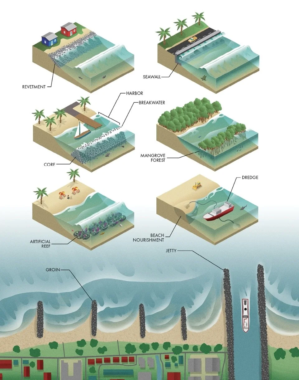
One of the most basic coastal structures is a revetment, a simple layer of hard armor atop a natural slope. Revetments usually feature large stones or concrete blocks that can withstand the constant force of crashing waves and tidal currents. Using blocks or stones can also absorb the energy of each wave, reducing the distance it travels up the slope. Similar to a revetment, a seawall, is a vertical structure parallel to the shore, protecting upland areas against erosion. Seawalls are usually constructed using reinforced concrete. Many seawalls feature a shape called a recurve to redirect wave energy back toward the sea, reducing the likelihood of water crashing over the top. Seawalls are usually constructed to an elevation above the normal high tide to protect against flooding and storm surges. They typically separate the developed areas they protect above from the sandy beaches below.
Breakwaters are another type of parallel structure used to protect areas of the shore from waves. Unlike revetments and seawalls, they aren’t connected to the shore. Instead, breakwaters are constructed offshore to dissipate wave energy and create areas of tranquil water for ships and structures along the coast, called harbors. Breakwaters can be made from many materials, but they are most commonly mounds of rock rubble. Often the core of the breakwater uses smaller rocks to reduce the flow of wave energy through the structure, while the outside layer consists of larger stones that can better withstand the waves.
Another protective structure, called a groin, protrudes into the sea to combat longshore drift, the process of sediment movement parallel to the coast. Like breakwaters, groins are usually made using mounds of rock or rubble. Over time, a groin will trap sand suspended in ocean currents to create a beach (a process called accretion). If properly sized, a groin can also protect the area on the downdrift side by reducing the speed and power of ocean currents along the shore. However, an oversized groin will rob currents of all their sediment, leaving none to replenish the beaches beyond and thus accelerating erosion along unprotected shores. After one groin is built, additional groins are commonly needed to protect the downdrift area, eventually leading to saw-toothed beaches extending for great distances.
Jetties are structures constructed perpendicular to the coast. They are often built in pairs to protect the inlet to a navigation channel by extending its mouth into the sea. Not only do they block the passage of sediment into the channel, but they also confine the flow of seawater within during tide changes, speeding it up to flush sediment from the bottom and minimize its accumulation.
Mangrove forests, and their dense networks of roots absorb wave energy and protect the soil along the coast.
Artificial reefs that provide habitat for fish, corals, and other marine life. Many materials have been used to construct artificial reefs, including rocks, concrete, shipwrecks, and even submerged subway cars. These reefs offer surfaces where marine organisms can attach or hide, with a secondary benefit of dissipating wave energy offshore, serving as submerged breakwaters.
Beach Nourishment: The process of replacing lost sand at beaches.
Concrete blocks (‘armor units’): Geometrically shaped structures that allow them to entangle and interlock to resist powerful hydrodynamic forces.
6 Coastal Shore Protection
Ports
Moving one ton of goods the same distance on a boat takes roughly half the amount of energy that it would by train and approximately a fifth of the energy it would take on a truck.
Ports: The hubs that connect maritime and overland modes of transportation.
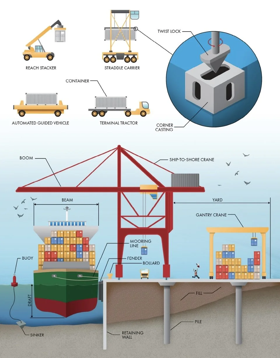
Bulk carriers, which transport unpackaged cargo like grains and ore, are serviced using large conveyors or bucket cranes. Tankers, which carry liquids like oil, are filled and drained by massive hoses. Most cargo ships that move packaged goods use containers, standardized steel boxes that can be easily transferred between trains, trucks, and other vessels using cranes.
The terminal is usually called a wharf or quay. The wharf may include one or more berths, which are parking spots for ships. Each berth includes several large bollards to which the ship’s mooring lines are attached. Winches on the ship keep these lines taut to minimize movement during loading and unloading. In addition, fenders along each berth serve as cushions to protect both the wharf and the vessel’s hull from damage.
One of the most critical decisions in the design of a port facility is the largest ship that can be accommodated, called the design vessel.
Depth is maintained in ports and channels by dredging sediment from the waterway floor using excavators or suction pipes.
A load (‘Plimsoll’) line, usually denoted as a horizontal line through a circle, will fall below the water if the vessel is overloaded.
6 Port Layout
Locks
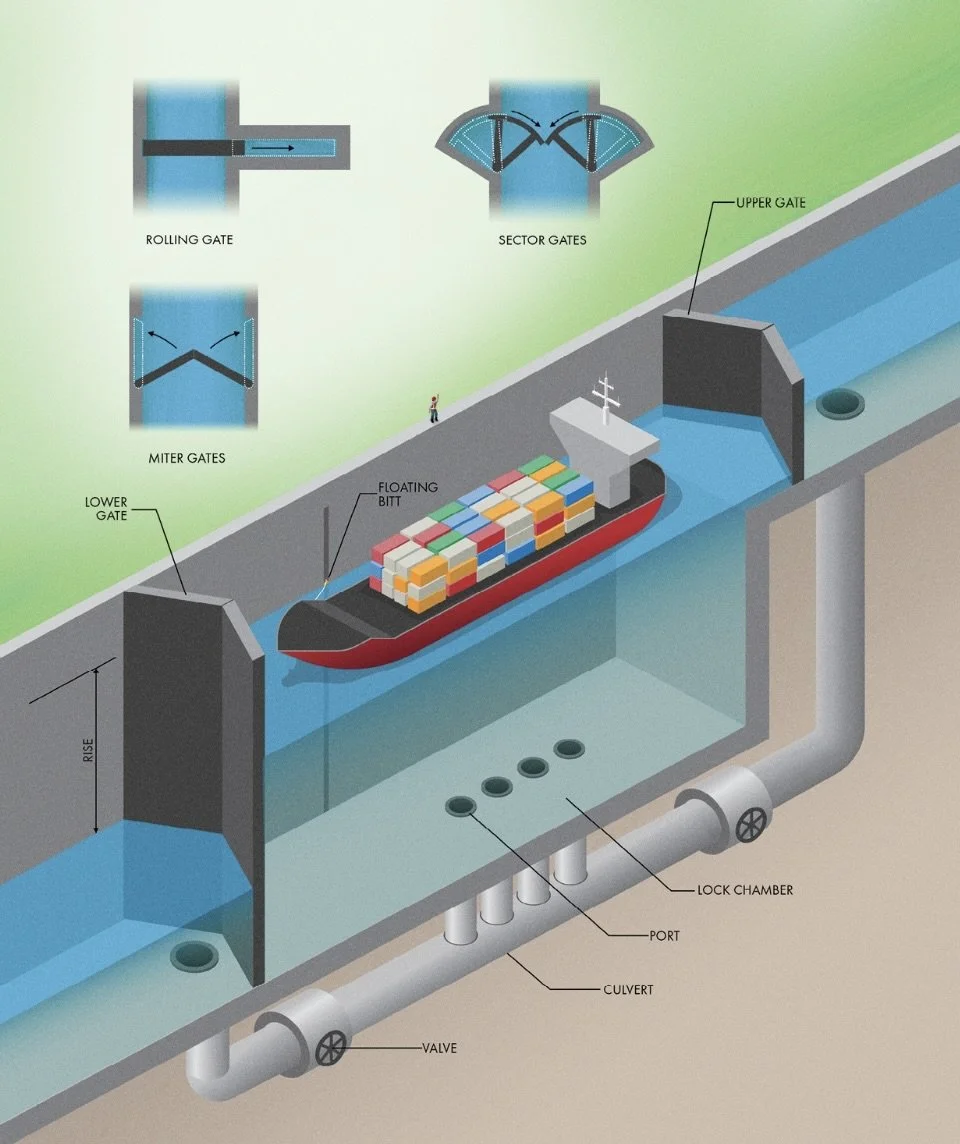
An ideal canal would sit at the same level for its entire length, but in areas with steep terrain, that would require so much excavation that it would be practically impossible. Rather than cut massive canyons to keep canals at a consistent elevation, we move ships up or down to different levels like steps on a staircase using navigation locks.
Most locks use miter gates. They are composed of two leaves, like enormous, hinged doors that close toward the center. Instead of closing in a straight line, the leaves meet at an angle pointing upstream. Pressure from the water above forces the gates tightly closed, keeping them sealed and leak-free during the operation of the lock.
6 Canal Construction
Levees and Floodwalls
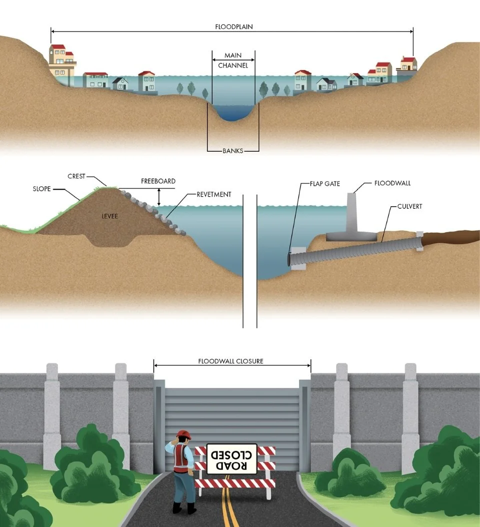
The most common way to raise the banks of a river is simply to gather nearby soil and pile it into an embankment. These structures, called levees (‘dikes’), have been used for centuries to divert and impound water. They are also used along coastal areas to protect against storm surge.
Levees subject to longer-duration floods or high waves may include stone or concrete armoring, called revetments.
Although relatively inexpensive and straightforward, levees take up a significant amount of land due to their trapezoidal shape. A more expensive but space-saving alternative is to build a floodwall. These walls are typically made from reinforced concrete and serve the same purpose of raising the banks of a river to keep the flow contained. They are also less susceptible to long-term deterioration because they are built from more resilient materials than compacted soil. The height of a levee or floodwall is a critical decision. The potential magnitude of flooding is almost limitless.
In the USA, many levees and floodwalls are designed to guard against the 100-yr flood- the height at which a theoretical storm has a 1% chance of being equaled or exceeded in a given year at a certain location. To set the crest of a levee or floodwall, engineers use historical flooding records and hydraulic models to estimate how high the 100-year flood would reach along a river. Then they add a little extra, called freeboard, to account for uncertainty and to keep waves from overtopping the structures.
Although levees protect low-lying areas from flooding, they can create new issues too. Since levees constrain the power of a river to a smaller space, the water flows higher and faster than it would have without such structures, potentially exacerbating flood impacts farther downstream.
To protect from flooding, sandbags are typically filled about half full, so it conforms readily with neighbor bags without leaving significant gaps.
6 Floodplains and Floodwalls
Concrete Dams
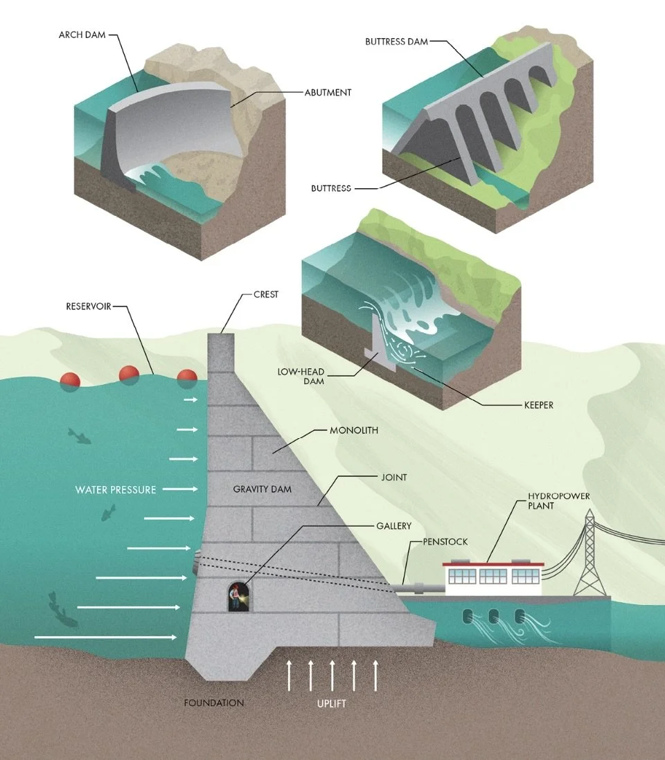
Building a dam across a river valley creates a reservoir, a place where water is stored and can be used over time for irrigating crops, providing water to cities, or generating electricity. A reservoir can also be kept empty in anticipation of severe weather, allowing a dam to hold back flood waters and release them gradually, reducing the damage they inflict downstream.
Many large dams serve multiple purposes at once using different zones within the reservoir, called pools. One pool can be kept full to be used for hydropower or water supply, and one above kept empty to be used for storage in the event of a flood.
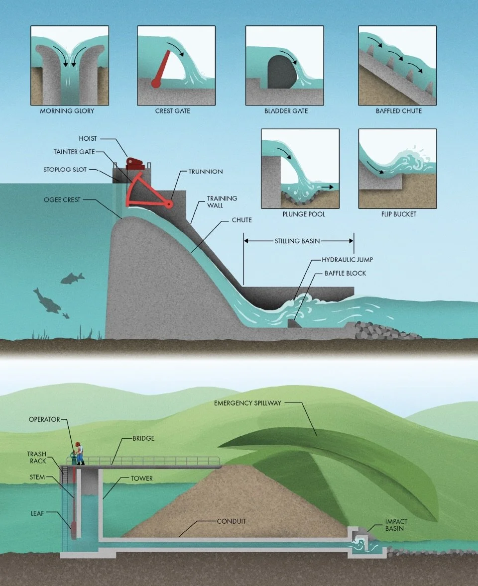
In a dam, large-diameter pipelines deliver water to the turbines, called penstocks.
Water can leak through pores and cracks in a dam’s foundation, creating pressure on the bottom of the structure, called uplift.
Gravity dams oppose the force of impounded water simply with their weight.
Buttress dams transfer the forces from the reservoir into the foundation using triangular buttresses. Buttress dams require less concrete to construct, but they also require more labor to form the intricate shapes needed for stability, so they are generally not economical in modern times.
Arch dams transfer much of the force from impounded water into the abutments on each side of the dam instead of the foundation. Arch dams take advantage of geometry to span a gap. Because they don’t rely as much on their own weight, arch dams need less concrete and thus can be more economical to construct.
Many concrete dams have internal tunnels, called galleries, to collect any leaking water and allow engineers to monitor the structure’s integrity from the inside.
Low-head dams impound a small volume of water, artificially raising the level to make a channel more navigable by boats, increase the depth at intakes for water supply and irrigation, or create a drop for powering turbines or waterwheels. Low-head dams are often called weirs because water flows over the top (rather than through a gate or outlet). As the jet of water (called the nappe) flows over a low-head dam and plunges into the river below, it can create an area of recirculation immediately downstream of the dam. This area is sometimes called a keeper because it can trap objects, debris, and even people.
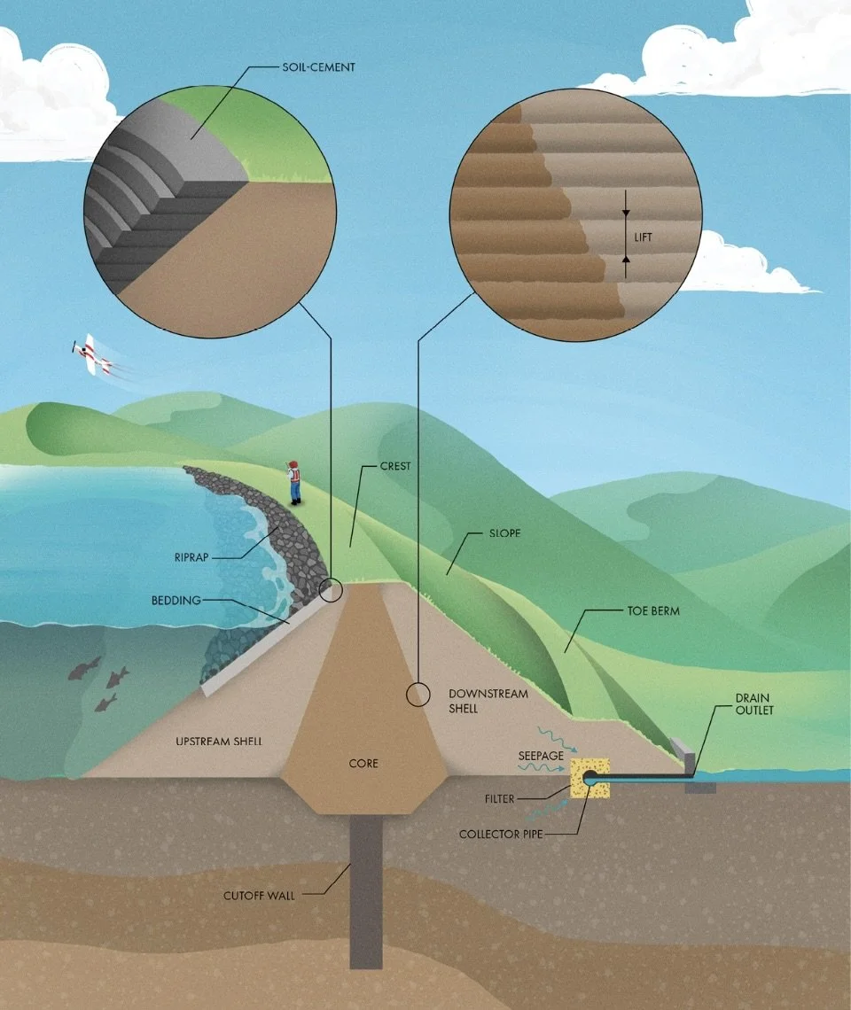
Embankment Dams
Embankment dams can be constructed out of soil, called earthfill, or out of stones or gravel, called rockfill. Both types of material behave much differently than concrete. Because they are granular substances composed of individual particles, earthfill and rockfill are naturally unstable. Gravity is always trying to pull them apart, and the only force holding an embankment together is the friction between individual grains or rocks.
Toe Berm: An area of additional fill along the bottom of one or both slopes to stabilize the structure further.
Modern construction equipment can compact a layer of soil up to ~30 cm thick at a time. Rolling over thicker layers will only densify the surface, leaving the underlying ground loose. So, embankments are constructed slowly from the bottom up in individual layers called lifts.
Most earthfill dams have different zones of material. The core is constructed using clay soils that are highly impermeable to seepage. Nearly all large earthfill dams will have some kind of armoring on the upstream face to protect against long-term damage from waves. Often this armoring consists of a thick layer of rocks called riprap. A layer of smaller gravel called bedding sits between the dam and larger rocks to prevent soil from washing out from under the riprap. Alternatively, many dams use a mixture of onsite soil and cement, forming an inexpensive but durable armoring called soil-cement.
Some dams and other artificial barriers in rivers are equipped with fishways (‘fish ladders’) to provide a bypass to the other side. Although various designs are used, most feature a series of pools with low jumps or cascades through which fish can leap.
6 Embankments
Spillways and Outlet Works
Outlet Works: The facilities that release water from a reservoir to meet downstream needs. The primary features of outlets are the gates and valves that control the flow of water.
All dams are designed with at least one spillway, a structure that can safely discharge water downstream when the reservoir is already full. Because of the inflow variability, many large dams have 2+ spillways. The smaller one is called the principal or service spillway that passes normal inflows when the reservoir is full. The other is called the auxiliary or emergency spillway that engages only during extreme events.
Hydraulic Jump: A dangerous water feature that occurs when fast-flowing water transitions into a slower stream.
___________________________________________________________________________
Ch 7 Municipal Water and Wastewater
Intakes and Pumping Stations
The deepest part of a natural channel (the ‘thalweg’) is often in the center, so bank intakes often require dredging of the riverbed to allow water to flow when the river level is low. One solution to the challenges of varying water levels and sediment buildup is constructing a small weir downstream. Such a structure raises the water level in the river while also slowing down the flow so that sediment can settle out. Modern intake structures on rivers make use of careful siting to avoid problems with sedimentation and lower water levels while minimizing environmental impacts.
Most water intakes are accompanied by a pumping station, which lifts the water from its source into a pipeline or aqueduct. Pumps are often installed directly above or adjacent to the intake structure, sometimes within a building called a pump house. These structures may be recognizable by built-in gantry cranes that allow equipment to be serviced or replaced when needed. At a pumping station, water flows into ports, through a conduit or tunnel, then into a structure called a sump (or wet well), which creates enough volume and depth for pumps to operate.
Certain types of organism- including mussels, snails, and clams- can cling to water infrastructure, clogging intakes and reducing the efficiency of pipelines as they accumulate (a process known as biofouling).
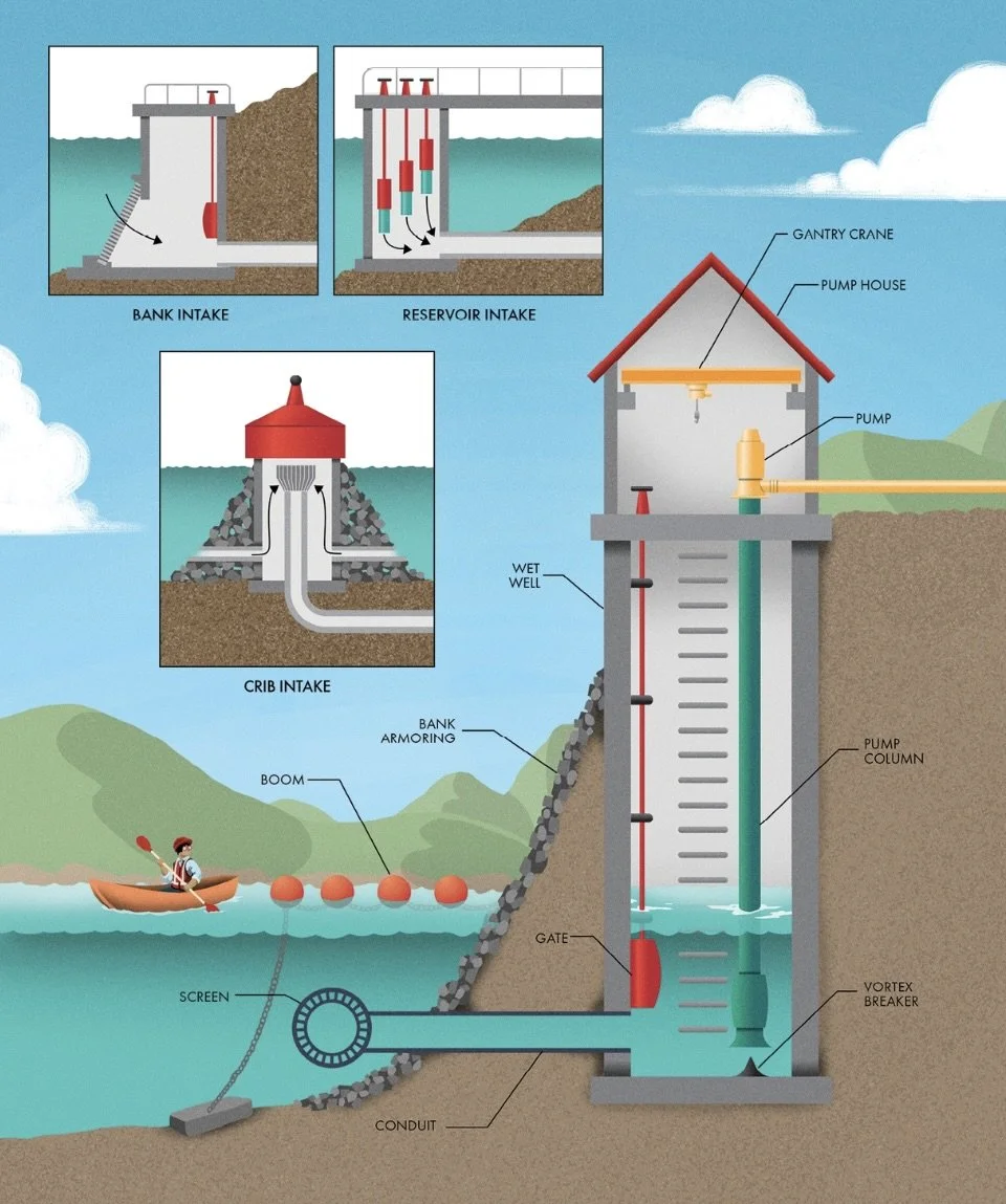
7 Intake and Pumping Station
Wells
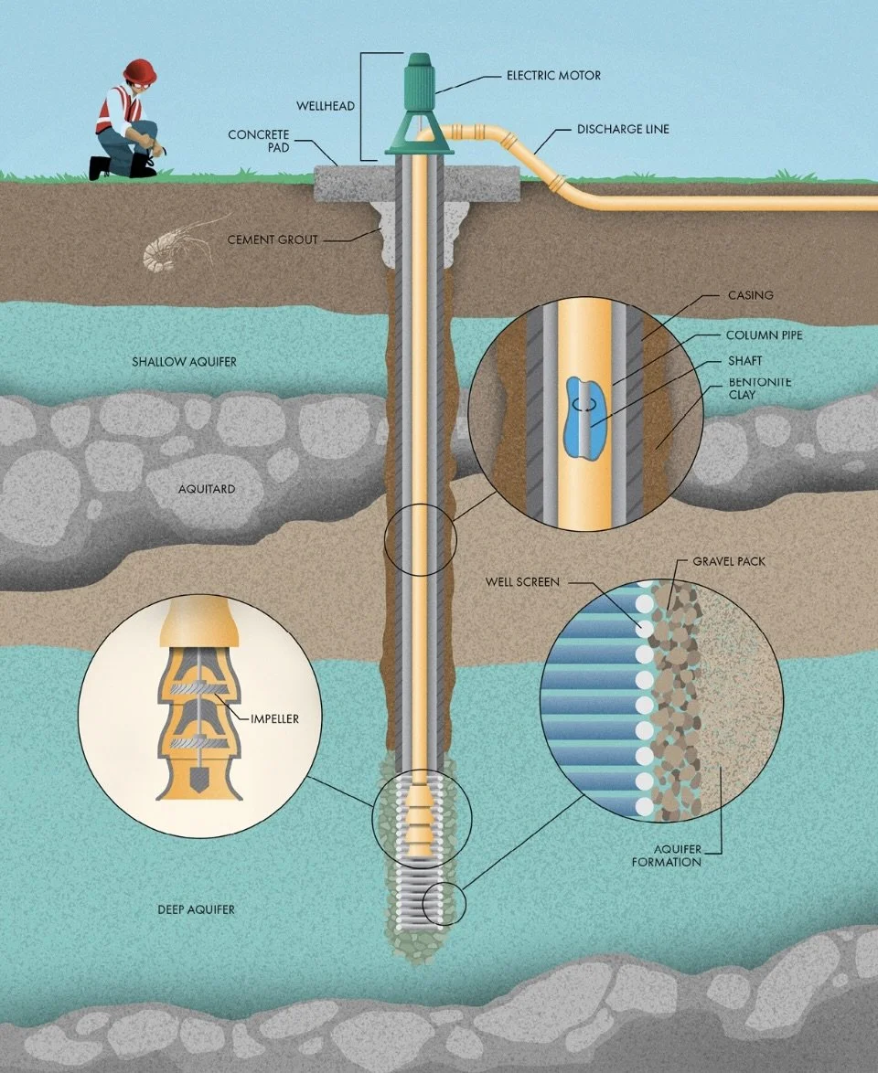
Groundwater reaches a less permeable geologic layer (called an aquitard) and cannot continue downward. Over long periods of time, infiltrating water can accumulate into vast underground resources called aquifers. Nearly all groundwater aquifers are geologic formations of sand, gravel, or rock that are saturated with water, like a sponge.
Once a borehole is excavated to the proper depth, a well can be installed. Steel or plastic pipe, called casing, is placed into the hole to provide support so that loose soil and rock can’t fall into the well. A screen is attached to the casing at the depths where water will be withdrawn. The screen allows groundwater to flow into the casing while keeping larger soil and rock particles out of the well where they could contaminate the water or cause additional wear on pumps. Once the casing and screen are installed, the annular space (the area between the excavated borehole and casing) must be filled. Where the well is screened, this space is usually filled with gravel or coarse sand called gravel pack. This material acts as a filter to keep fine particles of the aquifer formation from entering the well through the screen. The space along unscreened casing is usually filled with bentonite clay, which swells to create an impermeable seal so that shallower groundwater (which may be lower quality) can’t travel along the annular space into the screens. Finally, the uppermost section of the annular space is permanently sealed, again using bentonite clay or sometimes using cement grout. This seal ensures that contaminants on the surface cannot find their way into the well.
After a well is installed, it is usually taken through a procedure called well development to establish a hydraulic connection with the aquifer. Development involves surging water or air into and out of the well to remove fine sediments along the contact between the gravel pack and aquifer formation.
Shallow wells can use jet pumps that draw water up using suction like a straw. Deeper wells cannot use suction to bring water to the surface. Instead, the pump must be installed at the bottom of the well so that it can push water to the top. High-capacity wells are usually equipped with vertical turbine pumps. An electric motor is mounted to the wellhead and connected to a vertical shaft running down through the center of a column pipe. At the bottom, the shaft drives a series of impellers that force water from the well up through the column pipe into the discharge line. Vertical turbine pumps are easy to service since the motor is accessible at the surface.
7 Groundwater Wells
Transmission Pipelines and Aqueducts
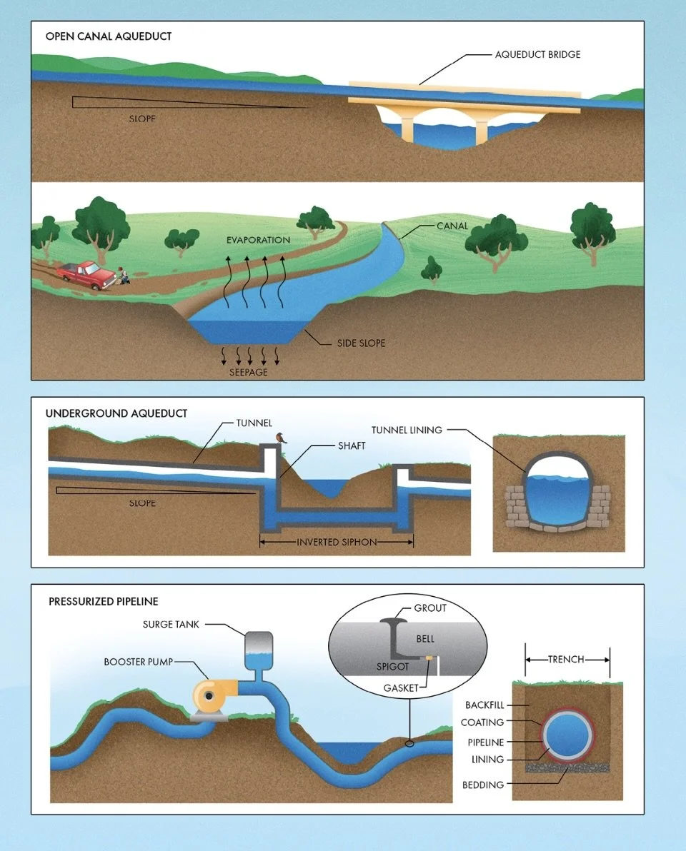
An aqueduct generally describes any human-made structure meant to deliver water across a long distance…Flow velocity in an aqueduct must be fast enough to minimize settling of silt on the canal floor but slow enough to avoid scouring and erosion. The channel also must be wide enough to carry sufficient flow without being so shallow as to accelerate the evaporation of water into the air or seepage into the soil below.
Most canals use a trapezoidal cross section with sloped sides that are less likely to collapse. Open canals are usually less expensive than other options, but they are subject to several disadvantages, including water loss through evaporation and seepage, freezing conditions that can block the flow, and their vulnerability to pollution.
When the source water is lower in elevation than its destination or the terrain along the way undulates too much for gravity flow, a pressurized pipeline may be the only feasible way for an aqueduct to function. A pumping station at the intake forces water into the pipeline, allowing it to flow against gravity.
Water pipes must be strong enough to withstand both the internal water pressure and external forces from the backfill and surface loads. Pipes must also resist corrosion from the water they carry inside and the soil along the outside. A pipe can be made from various materials, including steel, plastic, fiberglass, and concrete, and all materials have advantages depending on the situation. Larger pipelines often use protective outer coatings and inner linings to extend the lifespan of the line…When the spigot of one pipe section slides into the bell of another, it compresses a rubber gasket, creating a watertight seal. A band of grout is sometimes installed around each joint to protect the gasket and any exposed steel from damage and corrosion.
Water loses energy through friction, and these losses increase with velocity. Booster pumps along the way maintain pressure in the system.
The mass of fluid in a long pipeline can be enormous, sometimes greater than a fully loaded freight train. When all that water is moving through a pipe, it has quite a bit of momentum. However, even though it’s a fluid, water isn’t very compressible, so closing a valve or stopping a pump gives that momentum nowhere to go. Instead, it creates a spike in pressure that travels as a shockwave through the pipe, an effect called water hammer.
Air pockets can completely block a pipeline (an effect called air lock). Many pipelines are equipped with air release valves that can automatically vent bubbles from high spots in the pipe while keeping the water inside.
7 Aqueducts
Water Treatment Plants
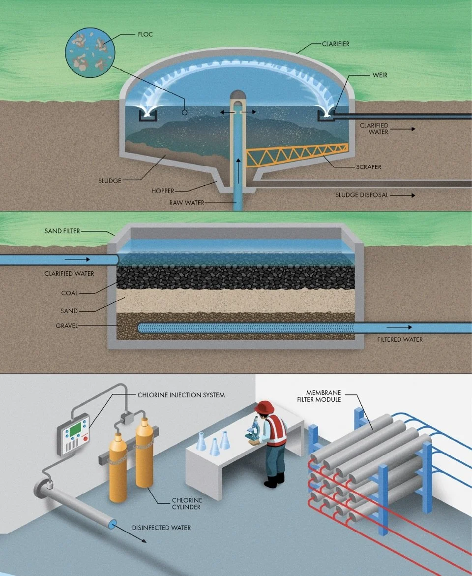
Groundwater and surface water both contain suspended particles of various materials. These solid particles give the water a murky appearance (called turbidity) and can harbor dangerous microorganisms.
The first step in most treatment plants is to remove these suspended particles from the water in a process called sedimentation, which is often accomplished in a series of three stages. First, a chemical coagulant is vigorously mixed into the water. Coagulants neutralize the electric charges that cause suspended particles to repel each other, allowing them to stick together. Next, a chemical flocculant is added to the water, which bonds suspended particles together into groups called flocs. Flocculant is added to the raw water slowly to avoid breaking up the flocs. As the flocs of suspended particles grow, they eventually become heavy enough to settle out (the third and final step of sedimentation). Raw (‘untreated’) water is pumped to a basin where it can sit nearly motionless while the flocs fall to the bottom. This basin can be as simple as a rectangular concrete box that’s regularly drained and cleaned, but many water treatment plants use tanks called clarifiers that include mechanisms to collect the solids as they settle at the bottom automatically. These circular basins are a recognizable component of many water treatment plants. The raw water flows up through the center of the clarifier and slowly makes its way toward the outer perimeter, dropping particles that form a layer of sludge at the bottom. The clarified water passes over a weir so that only a thin layer farthest from the sludge can exit the basin. A scraper pushes the sludge down the sloped bottom of the clarifier into a hopper where it can be collected for disposal.
Sedimentation removes most suspended solids, but it can’t completely clean the water of tiny particles, viruses, and bacteria. Most water treatment plants follow sedimentation with a process of filtration, which involves forcing water to pass through porous media. The filters in municipal treatment plants commonly consist of layers of sand, coal, or other granular materials. The water flows by gravity or under pressure from pumps through the filter media while undesirable particles within the water are left behind. A layer of gravel prevents any of the media from washing out with the filtered water. Over time, solids accumulate within the filter media, reducing its efficiency. Filters are backwashed by sending water through the opposite direction to clean the media. The backwash water is sent back to the treatment plant inlet to be reprocessed…Some modern treatment plants have abandoned traditional sand filters for membranes, which consist of thin sheets of semipermeable material. Pressurized water is forced through the tiny pores in the membrane, leaving any unwanted particles behind. Water treatment plants using membrane filtration usually have a rack of tubular filter modules, allowing quick replacement of individual units if they clog or malfunction. Membrane filters can remove even the tiniest contaminants (including even viruses), so they are sometimes preferred over using multiple separate treatment processes to create potable water.
The final step of a typical water treatment plant is disinfection, where any remaining parasites, bacteria, and viruses are killed. There are several methods for deactivating microorganisms to make water potable, but the primary tool used in most cities involves adding a disinfectant chemical to the water (usually either chlorine or chloramine). These chemicals are safe for human consumption at low concentrations while still killing microorganisms that can make us sick. Many treatment plants use chlorine gas stored in metal tanks called cylinders. An injection system carefully feeds the gas at a predetermined rate where it dissolves into the water and kills disease-causing pathogens.
Chlorine that stays in the water is called the residual, and it is a critical indicator that a water treatment and distribution process is operating effectively…Many cities use booster chlorination stations in strategic locations to provide a more uniform distribution of disinfectant.
7 Water Treatment Plant
Water Distribution Systems
A municipal water distribution system consists of all the interconnected pipes, valves, and other elements that combine to carry clean water used for drinking, cleaning, cooking, watering plants, and a wide variety of commercial and industrial processes.
The first step in a water distribution system is usually the pumps, which do the job of pressurizing pipes within the system, usually to between 2-6x normal ATP, which is why they are often called high-service pumps…High-service pumps used in water distribution systems consume significant amounts of electricity, so they often require robust connections to the electrical grid and backup generators for potential outages.
From the pumps, clean water enters a series of pipes called water mains, the circulatory system for potable water within a city. Water mains are usually installed belowground to protect them from damage and, more important, from freezing. Most mains are connected in a grid or loop pattern, often following the paths of city streets.
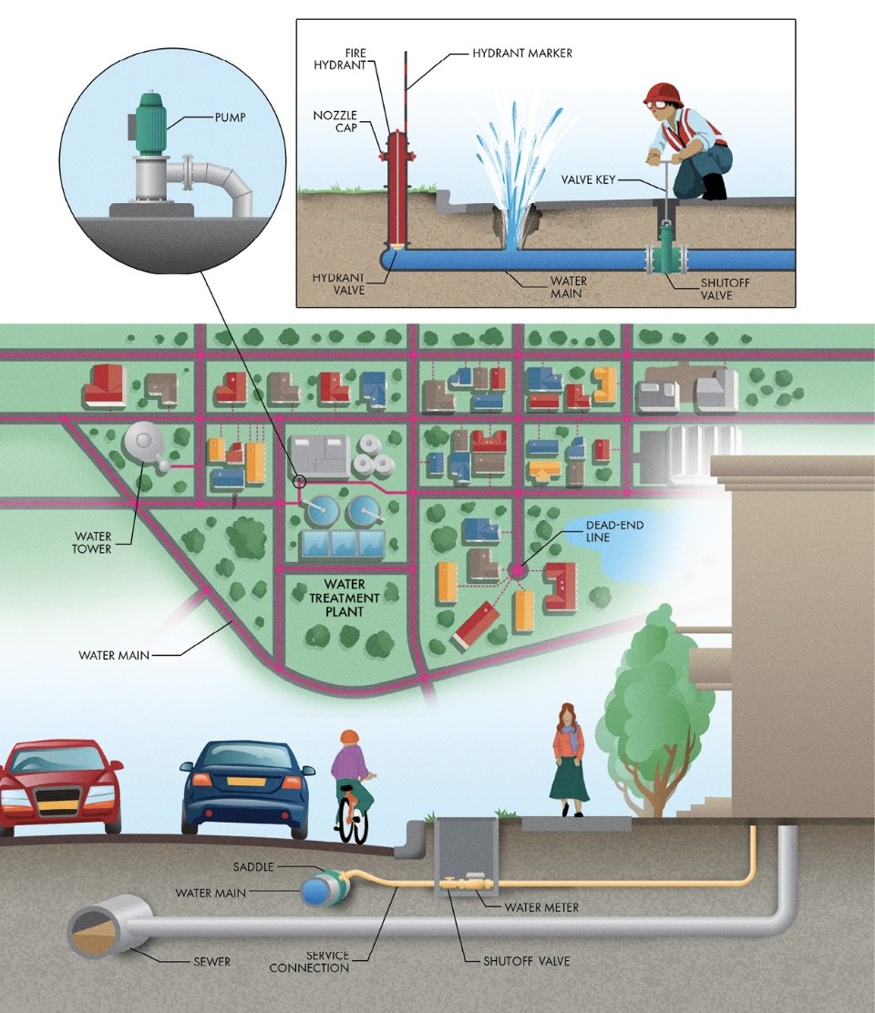
Individual customers get their water from the main lines through service connections. A saddle is used to create a tap point to the main line. Piping usually runs from the saddle to a water meter that measures the volume of water used, allowing the utility to charge each customer based on usage.
Although repairing a line while it’s discharging a geyser of water is possible, it’s usually a difficult ordeal. Isolating the main from the rest of the system before starting repairs is much easier. Shutoff valves are typically located at intersections in water mains to allow parts of the network to be disconnected so crews can fix a broken pipe. Valves are installed in belowground enclosures with small steel lids.
Cities are dotted with fire hydrants that provide connection points to pressurized water mains to help extinguish fires. Most places in the USA use dry-barrel hydrants, which have their valves located belowground, protecting them from damage due to errant vehicles and reducing the chance of water freezing within the exposed hydrant.
Lead is a durable metal while still being flexible enough to make pipes easy to bend. However, even at low concentrations, exposure to lead is dangerous to human health and can cause neurological effects, especially in children. Lead can leach into water traveling through pipes, exposing humans to this hazardous contaminant…Some cities introduce corrosion-inhibiting chemicals in the water to reduce the chance of leaching lead from the pipes before they can be replaced.
7 Water Delivery Infrastructure
Water Towers, Tanks, Sewers
Many types of storage structures are used in water distribution systems. Ground-level tanks often consist of large, circular steel or concrete enclosures. Many tanks include a level indicator on the outside to show the water level at a glance. Some cities use ground excavations to form ponds called finished water reservoirs that hold significant volumes at a relatively low cost. These ponds are often lined with plastic or concrete to prevent leakage and are covered to minimize the chance of contamination. Both ground-level tanks and reservoirs can often be seen at water treatment plants, where they are known as clearwells.
Large cities often use elevated storage tanks, also known as water towers, that have their entire storage volume well above the minimum system pressure…The water surface in elevated storage tanks represents the surface of the virtual ocean (called the hydraulic grade line by engineers).
A water tower is as simple as a tank connected to a water main. When water demands fall below the pump capacity, the pressure in the system goes up, forcing water into the tank through the inlet/outlet pipe. When demands rise above the pumping rate, the system pressure goes down, and water flows out of the tank through the same pipe to supplement water from the treatment plant…Most tanks feature an overflow to prevent them from overfilling. Vents make sure that the air pressure in the tank doesn’t change with the water level, potentially creating positive or negative pressure that could damage the structure. Access hatches provide means for maintenance and inspection inside the tank.
Most tall buildings have their own system of pumps and tanks to ensure that each floor has adequate water pressure.
Sewers rely on gravity to do the work of collecting and transporting waste, flowing downward, converging, and concentrating into larger and larger streams. Sanitary sewer networks are dendritic with small pipes at individual buildings concentrating into larger and larger lines until all the wastewater converges at a single treatment plant. Pipes that service individual buildings are usually called laterals, and those servicing particular streets are branches. Larger pipes that collect wastewater from multiple branches are called main sewers or trunk sewers. The most significant lines and the farthest downstream in the system are usually called interceptors.
Any time the size or direction of a sewer changes and at intersections of pipes, a sanitary manhole is installed to provide access for maintenance and inspection. Manholes are usually made from vertical concrete enclosures that run up to the ground surface. Steps allow personnel to enter and exit. A heavy cast iron plate, called a cover, keeps people and debris out of the sewers while allowing vehicles to drive over the top. Manholes also sometimes serve as vents to equalize the air pressure within the lines and prevent the buildup of toxic gases.
A typical wastewater lift station consists of a concrete chamber called a wet well. Sewage flows into the wet well by gravity via the inlet sewer, filling it over time. Once the level reaches a prescribed depth, a pump turns on, pushing the wastewater into a pipe called a force main.
Sewage is a slurry of liquids and solids from a wide variety of sources. Lots of stuff ends up in our wastewater stream, including soil, soap, hair, food, wipes, grease, and trash. These things may make it down the toilet or sink drain and through the plumbing in your house with no problem. However, in the sewer system, they can conglomerate into large balls of debris (called pigtails or fatbergs by wastewater professionals).
Most sanitary systems are separated from storm drains, which carry away rainfall and snowmelt.
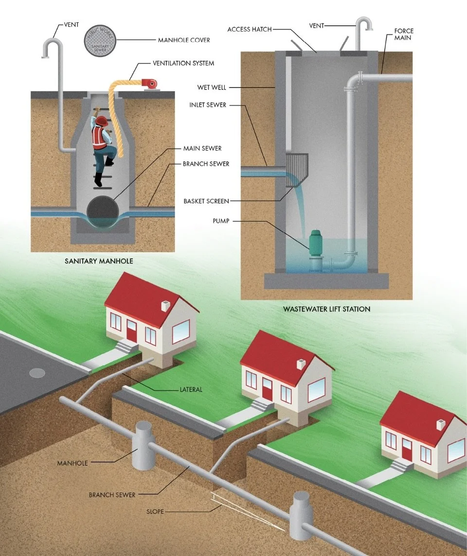
7 Sewer Systems
Wastewater Treatment Plants
Nearly all wastewater collection systems rely on some kind of treatment plant to reverse the dirtying process, removing contaminants from sewage water so it can be reused or released back into the environment as processed water (‘effluent’).
The initial steps in a water treatment plant, called primary treatment, involve the physical separation of contaminants that are suspended in the swift and turbulent flow. First, sewage flows through a bar screen that filters out large debris like sticks, rags, and any other large pieces of detritus that find their way into the sewers. Many technologies exist, including bar screens equipped with automated rakes that scrape the filtered debris into a bin to be discarded as solid waste. Next, suspended particles are separated from the flow.
Sand and soil found in wastewater are collectively known as grit. These materials can damage equipment in the plant, so they are usually removed in a separate process during primary treatment. Treatment plants use grit chambers, often configured as long narrow tanks, to slow down wastewater flow. Within these placid conditions, suspended sediments will settle to the bottom of the chamber while the grit-free wastewater continues to the outlet. Some grit chambers introduce air bubbles that help fling heavier particles to the edges of the tank. Others use a motorized agitator to create a vortex in the flow to accomplish a similar feat. A sump at the bottom of the chamber collects the settled grit to be pumped away for disposal. The final step in primary treatment is also usually a gravity process. Wastewater leaving the grit chamber is still full of suspended solids, but they mainly consist of small, organic particles or floating oils and grease (collectively known as scum). Most treatment plants use primary clarifiers to separate these remaining solids. The large circular tanks slow down wastewater flow even further, allowing tiny particles to sink gently while a skimmer collects the solids floating on the surface. The solids are sent for further processing, and the clarified wastewater exits over a weir into the secondary treatment process.
Where primary treatment physically separates contaminants from wastewater, secondary treatment does so using biological processes, replicating what Mother Nature would do naturally but in a much shorter time period. Most wastewater treatment plants take advantage of microorganisms that can digest organic matter in sewage. As they consume contaminants, these bacteria and protozoa clump together, leaving relatively clean water behind. The microorganism communities that thrive in oxygen-rich (aerobic) environments are different from those that live in oxygen-depleted (anaerobic) environments. These various colonies consume different nutrients from the water, so treatment plants often utilize both aerobic and anaerobic conditions to remove wastewater contaminants thoroughly. Aerobic conditions are created in aeration basins where blowers generate a constant supply of air that passes through diffusers, creating tiny bubbles that mix and dissolve oxygen into the water…Once the biological treatment has consumed most of the nutrients, the cleaned water with suspended clumps of microorganisms (called mixed liquor) moves from the aeration chamber into a secondary clarifier. Here, the colonies of bacteria settle to the bottom, allowing only clean effluent to be discharged.
Most treatment plants perform a final disinfection to kill any remaining pathogens in the water. Disinfection may be completed using dissolved chlorine, ozone gas, or intense UV lights, which deactivate viruses and harmful bacteria. The final effluent from the treatment plant is usually discharged into a natural stream, river, or ocean.
Some of the microorganisms that settle out in the secondary clarifier (known as activated sludge) are returned to the aeration chamber to seed the next colony. The rest of the sludge must be discarded.
Rather than allow such decomposition to occur in a landfill, many treatment plants use digesters to process organic solids. Digesters convert sludge into biogas, which can be used as a fuel for heating or electricity generation, and a solid material called digestate (or biosolids), which can be dried and landfilled or used as a fertilizer.
Direct Potable Reuse (‘Toilet-to-Tap’): Sewage is cleaned to drinking water–quality standards and reintroduced to the distribution system.
Many wastewater treatment plants are now considered water reclamation plants because, instead of discharging effluent to a stream or river, they pump it to customers that can use it, hopefully reducing demands on the potable water supply as a result. In many countries, purple pipes are used to distinguish non-potable water distribution systems, helping to prevent cross-connections.
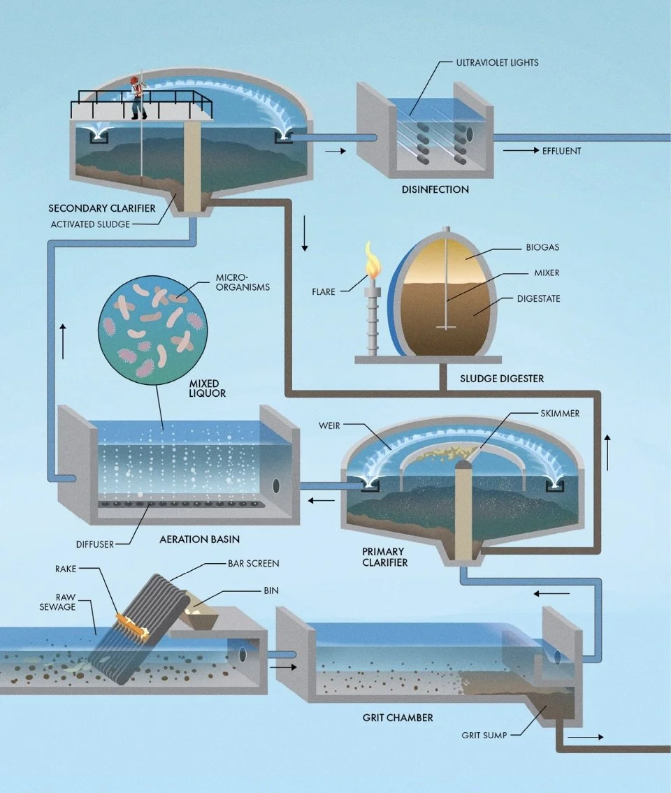
7 Sewage Treatment Plant
Stormwater Collection
In the past, it was common to simply put all the runoff from the streets directly into the sanitary sewage system. Unfortunately, wastewater treatment plants are usually not designed to process massive influxes of combined sewage and stormwater runoff at the whims of Mother Nature. In the worst cases, these plants have to release untreated sewage directly into watercourses when the inflow is too much to be stored or processed. That’s why most cities now separate storm sewers from the sanitary sewers used to carry wastewater.
A storm sewer system routs all runoff into a natural watercourse or the ocean. Energy-dissipating baffle blocks or rock riprap armoring are often installed at outfalls to protect the natural soils against erosion from the swiftly exiting runoff. Unlike a sanitary sewer system that terminates in a treatment plant, most stormwater runoff is discharged directly into the environment.
Many cities increase the capacity of natural watercourses by enlarging, straightening, and lining them with concrete. This design strategy is often known as channelization. Speeding up stormwater flow through channelization reduces the depth and extents of flooding, but it also has disadvantages. Dirty concrete channels hurt the visual character of a city. Channelization can also worsen flooding downstream and degrade the habitat of the original waterway.
Retention ponds maintain a permanent pool of water where detention ponds are ordinarily dry. Both act like mini sponges, absorbing all the rain that rushes off the buildings, streets, and parking lots. Their outlet structures are designed to slowly release runoff back into waterways, shaving off the peak flow rate to the level before all the buildings and parking lots were built. Retention and detention ponds also help reduce pollution by slowing down the water, so suspended particles can settle out.
Culverts: Allow water to cross below man-made features.
Rainwater is a resource, and natural watersheds provide many more services than simply conveying runoff downstream. They serve as habitat for wildlife, clean and filter runoff with natural vegetation, divert rain into the subsurface to recharge aquifers, and reduce flooding by slowing down the water at the source rather than letting it quickly wash away and concentrate.
Low Impact Development: (in the USA) practices that reduce the volume of runoff and the pollution it carries by managing it close to the source are collectively. Includes rain gardens, vegetated rooftops, permeable pavements, strips of vegetation used to filter surface runoff, and other ways to harmonize the built environment and its original hydrological and ecological functions.
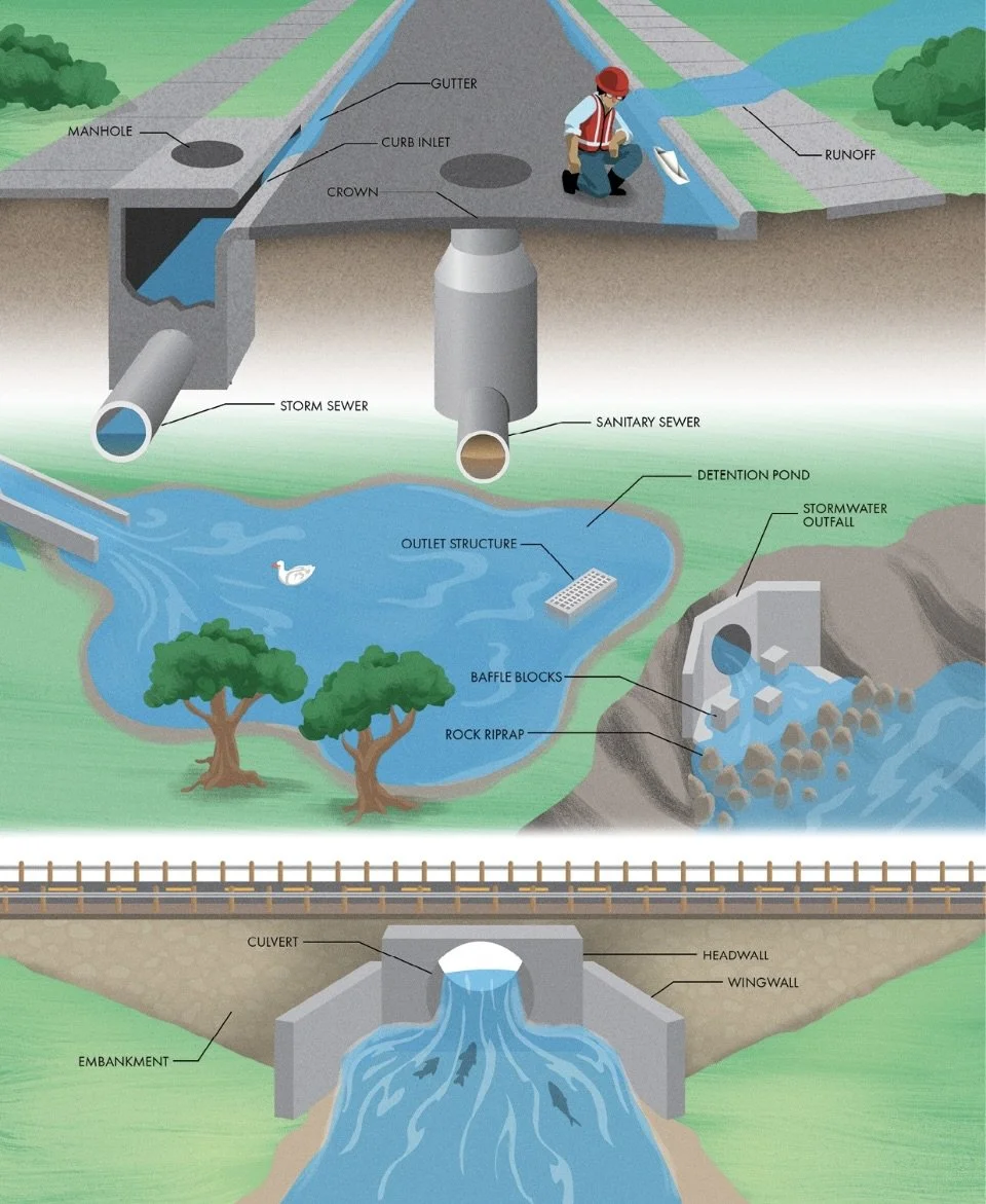
7 Storm and Sanitary Sewer Systems
___________________________________________________________________________
Ch 8 Construction
Typical Construction Site
Before construction can begin, a surveyor must lay out the location of the project on the ground. Surveyors install control points that can be used as a reference once construction begins. They are usually large nails driven into the underlying concrete or asphalt or iron rods driven into the soil. Surveyors often mark control points and other essential features of construction with wooden stakes and plastic flagging tape.
Linear construction projects like roadways and pipelines often use a coordinate system called stationing. In the USA, each station is equal to 100’. It’s common to see locations on a site labeled with their distance along the centerline of the structure in stations plus the number of feet (i.e., “STA 12+50” indicates a location 1,250 feet along the axis).
All subsurface utilities must be identified and marked to ensure that excavators don’t inadvertently damage underground lines. Locators use colored spray paint to create utility location marks on the ground. In many parts of the world, these colors are standardized. Red is used for electric lines, orange for telecommunications, yellow for natural gas, green for sewers, and blue for drinking water lines. White paint is used to show the location of any excavations that will take place during construction, and pink is reserved for survey markings.
A project sign is used to identify the companies involved, notify the public of the name and purpose of the project, and post important information such as building permits.
Much of underwater construction involves getting rid of the water first so that work can proceed in the dry, a process called dewatering. Often, a structure called a cofferdam is required to hold water back from a construction site temporarily. Cofferdams usually consist of earthen or rockfill embankments, interlocking steel plates called sheet piles, steel frames with a plastic membrane, or water-filled rubber bladders.
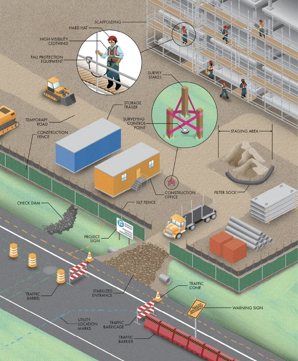
8 Construction Sites
Cranes
Mobile Crane: Cranes with wheels or tracks, allowing them to move to different parts of a site.
Crawler Crane: A crane that is mounted on an undercarriage with a set of tracks.
Rough Terrain Crane: Cranes that ride atop a mobile undercarriage, but they use rubber tires instead of tracks.
Tower Crane: A crane that that consists of a vertical mast and a horizontal jib extending out from the tower. The jib can rotate in any direction around the mast on a turntable. A trolley that rides along the jib allows the operator in the overhead cab to place the hook wherever needed.
Nearly all cranes have a drum onto which cabling is spooled. When a crane rotates the drum to lift a load using the cable, it is called hoisting…When the boom of a crane pivots up with a load, it is called luffing. Some cranes can luff the boom and jib separately, providing an even greater range of movement. Swinging the boom or jib horizontally is often called slewing. Finally, cranes with telescoping booms can extend or retract, and tower crane trolleys can travel inward or outward…Counterweights made from steel or concrete are used to balance the load on the hook, reducing the crane’s tendency to tip over (called its moment).
Slings are generally used in one of three basic hitches; in a vertical hitch, one eye of the sling is connected to the hook, and the other is connected to an attachment point on the load. In a basket hitch, the sling passes under the load with both eyes on the hook. Finally, in a choker hitch, one eye of the sling is wrapped around the load, passed through the other eye, and attached to the hook.
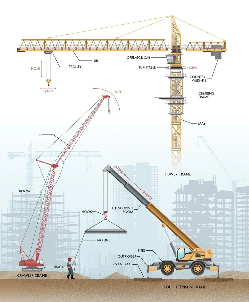
8 Cranes
Construction Machines
Excavators: Common vehicles that feature a bucket, arm, and rotating cab, although many other attachments and configurations exist. Excavators use their hydraulic cylinders to perform various functions, including digging holes and trenches, removing debris, and even lifting and placing loads like a crane.
Trenchers: Machines meant specifically for excavation. Trenchers use a toothed wheel or chain to cut long holes into the earth for installing pipelines, drains, electrical lines, and other linear utilities.
Dozers: Vehicles with large blades used to shove materials around. They can clear brush, trees, and boulders from a site, push soil across short distances, and spread fill over a large area. Like dozers, graders also feature a long blade. However, graders offer more precision, allowing operators to level (or grade) the earth with high accuracy. Instead of a blade, loaders are equipped with large buckets for excavating and transporting larger quantities of soil.
Pavers: Vehicles that make concrete structures and use a process called slipforming to create continuous shapes like curbs and highway barriers.
Roller Compactor: A heavy vehicle with smooth drums that compress the soil or asphalt as they roll over it.
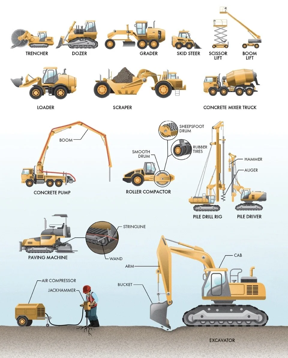
8 Construction Equipment
___________________________________________________________________________